Time to read: 6 min
In China Manufacturing parts’s 2016 State of Hardware Report, a whopping 70% of participants reported using Solidworks. Solidworks might be expensive and is certainly not perfect, but it sure is popular!
Considering how many people out there are using Solidworks, I thought it would be great to impart a few tips & tricks for upping your Solidworks game and becoming a pro.
Note: The purpose of this article is NOT to convince you or anyone else to use Solidworks over the many other options that are out there. This article is for people that have already chosen Solidworks (or had Solidworks chosen for them) and would like to greatly improve their skills.
1. Customize Your Toolbar
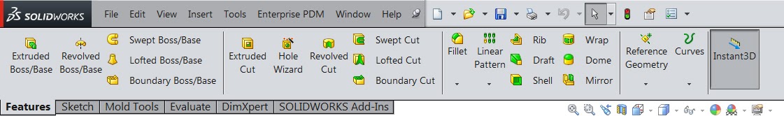
The Command Manager, shown above, is touted by Dassault Systèmes, the maker of Solidworks, as a simple and easy to use location for all the features, sketch tools and evaluation tools that you might need.
Simply put, it is for newbs. If you want to become a Solidworks pro, you should consider ditching the Command Manager in favor of a comprehensive and customized toolbar setup. It’s the quickest and easiest upgrade you can make.
Here’s an example of such a setup with a brief explanation of how it is broken down:
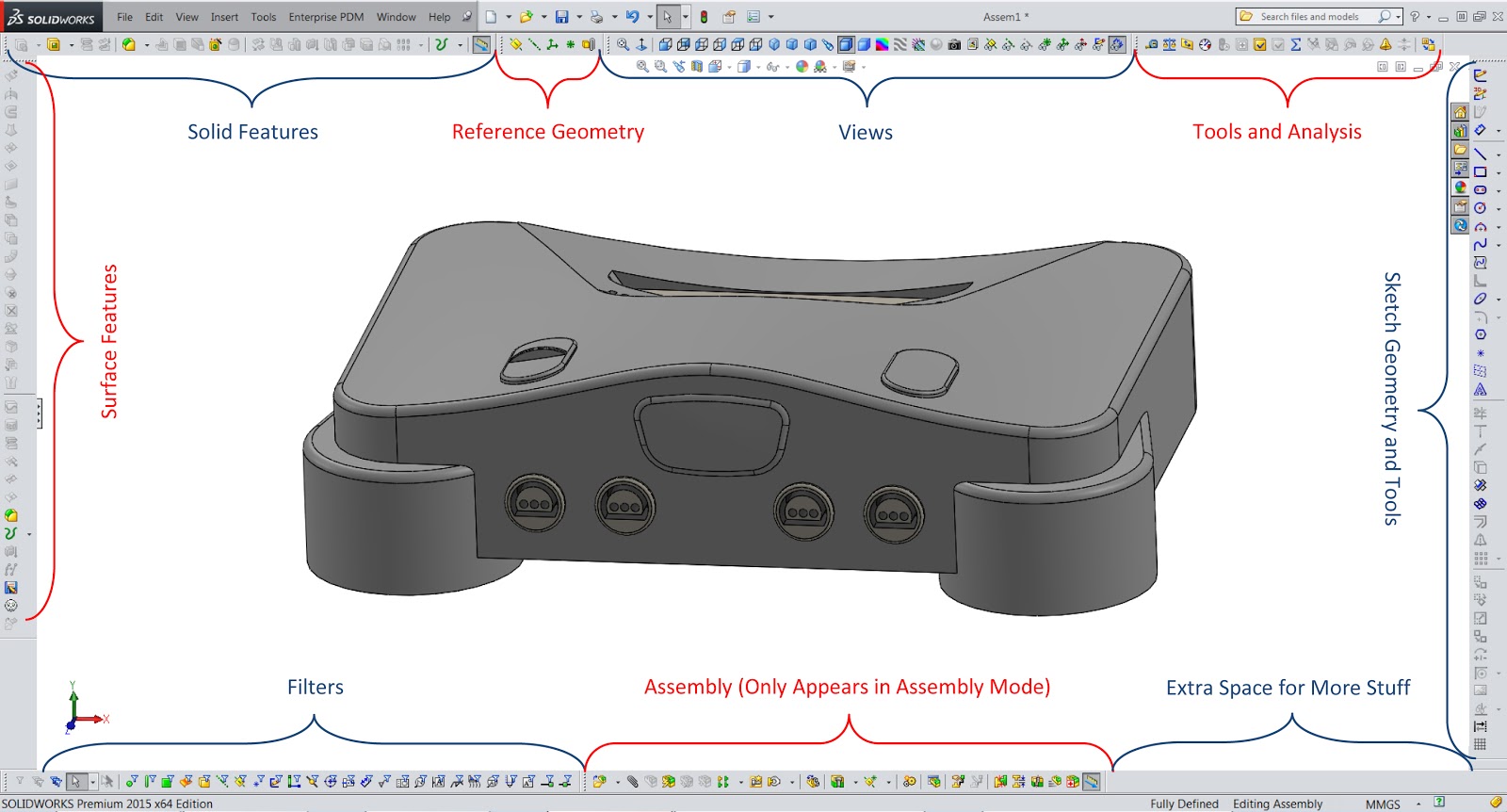
As you can see in the picture, the 3D model is surrounded by about 200 icons, that could each be used via a single click. Many of these features cannot be found in the Command Manager at all. For those that can be found there, they would have required multiple clicks to get to and use. Using this setup, or one like it, can save hundreds of clicks per hour!
It used to be that you couldn’t give up so much screen real estate for commands. However, with screens becoming as big as they are and with resolutions as high as they are, you will still have plenty of screen space for your 3D model and the feature tree itself.
2. Use a Maximum of 3 Points per Spline
Splines are great for creating organic shapes while still keeping good control over the results. However, too much control can negatively affect those results just as much as too little control.
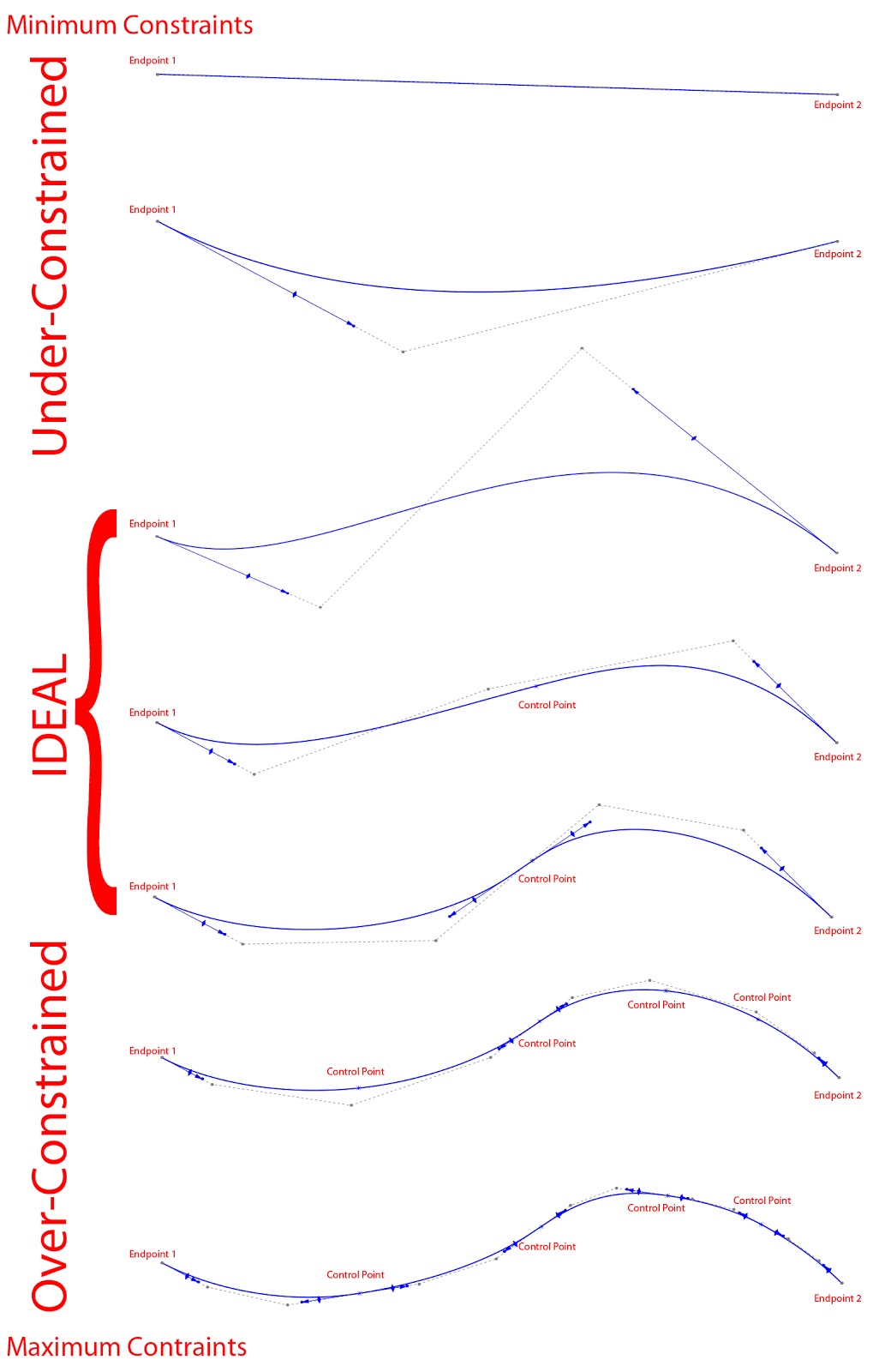
As a general rule, try to use as few spline points as possible while still achieving the desired result. I keep all of my splines limited to 3 points (both ends plus ONE control point somewhere in between). Solidworks will let you add as many control points as you want to, but I don’t recommend it.Adding more than one control point tends to over-control the spline (when using features such as lofts and sweeps), which will yield undesirable waviness or ripples in the resulting surface/s.
The picture below shows what happens to a spline as you add more and more constraints or controls to it. As you can see, not enough constraints yields a pretty uneventful spline. On the other hand, too many constraints will make the spline appear more jagged. Those somewhat jagged transitions are what cause undesirable waviness and ripples.
3. Trim, But Do Not Extend Spline Surfaces
As a general rule of thumb, spline surfaces can be trimmed as much as you want, but should not be extended past their original boundaries.
In reality, Solidworks will let you do both, but you should know that extending a spline shaped surface involves Solidworks doing a lot of math on what it thinks the spline shaped surface would look like if it were created as a larger/longer spline and then trimmed to the current spline. That math is difficult and the results are not so accurate.
Whenever possible, draw splines much longer than you think it needs to be when creating a spline shaped surface. Do whatever command you planned to do using that longer spline. Then, trim the end result.
In this case, I am NOT saying to trim the original spline drawn in the sketch itself. I am saying that you should trim the end result created using a longer spline. For trimming splines within sketches, see tip #4 below.
4. Use the Master Sketch Method to Trim Splines within a Sketch
Imagine you sketch a collection of splines that cross each other and you want to trim them together. Trimming these splines in a single sketch will automatically change the endpoints of those splines to where you trim them to.
This will change the way that the splines themselves are controlled/constrained because they are controlled by their endpoints, which are now different. This might not be what you intended.
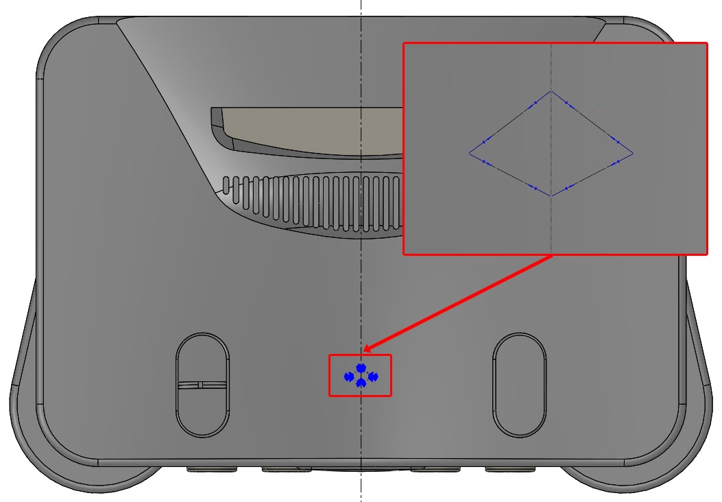
Here’s an example: Let’s say you want to add a recess for your company logo on your product. You want the recess to be a diamond shape, but you want the sides of the diamond to be somewhat curved. In fact, you want the sides of the diamond to be curved in relation to other aesthetic elements in your product. So, you draw a collection of fully editable splines as shown below:
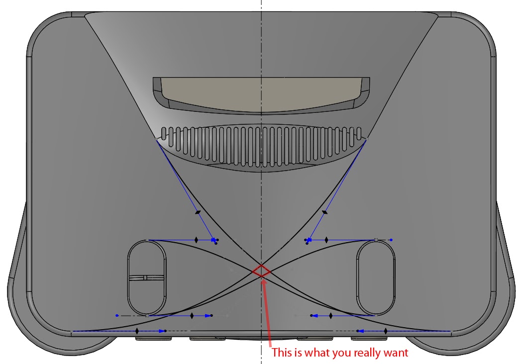
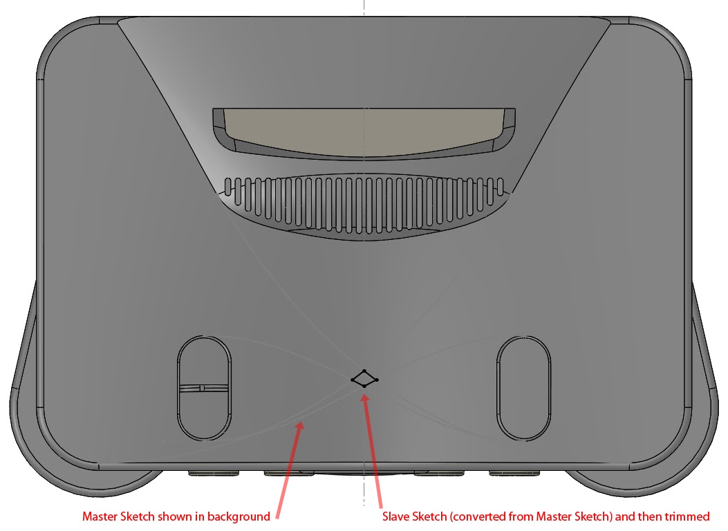
If you can tell from the image above, the original splines were set to tangent to geometry in the part itself. If you trim the splines so that only the curved diamond shape is left, the result is the same curved diamond, but the control points have moved to the corners of that diamond, as shown below.
Once you trimmed this splines together, you lost the method you used to control the shape itself. At that point, you would just be eyeballing any changes to the splines and hoping the results look good.
The solution to this problem is something I call the Master Sketch Method:
Step 1
Draw as much content as you want in a single sketch. Don’t worry about trimming lines or splines. Instead, leave them all their original length. Call this sketch your “Master Sketch”.
Step 2
Create a new sketch on the same plane (or a parallel one) and use the convert entities tool to convert some or all of the items in the Master Sketch into your new sketch. Call this new sketch your “Trimmed Sketch”.
Step 3
In the Trimmed Sketch, trim the converted entities from Step 2. Use this trimmed sketch for whatever feature you want.
Result
Your Master Sketch will be exactly how you originally drew it. Your Trimmed Sketch will be a trimmed version of the Master Sketch. Editing the Master Sketch will update the Trimmed Sketch, but the constraints intended for the splines are left intact.
A Few Notes
- This can be done for as many Trimmed Sketches as you want (maybe different variations of trimming the splines together).
- Editing the Master Sketch’s existing entities yields no rebuild issues unless you add or delete geometry from the Master Sketch.
- If you delete entities in your Master Sketch, the Trimmed Sketch/es will show those deleted entities as dangling. You would simply delete those entities from the Trimmed Sketch/es as well.
- If you add entities to the Master Sketch, it will update the Trimmed Sketch/es properly ONLY if you converted the entire Master Sketch at once. If you picked and chose what to convert and what not to, then your Trimmed Sketch will not automatically add the geometry you added to the Master Sketch. In that case, edit the Trimmed Sketch and use the Convert Entities tool to re-add the missing geometry from the Master Sketch.
Main Takeaways
Solidworks is a great tool for taking your ideas and turning them into digital 3D models that are ready for prototyping and production. Becoming familiar with the software’s lesser known abilities and limitations, such as the ones shown here, will help you take your ideas farther, faster. Good luck out there!
+ If you found this article interesting, check out How to Get the Most out of Surfacing in Solidworks.

