CNC machining is one of the most widely used prototyping and manufacturing methods today, especially for metal parts.
Most of the details, such as tooling, spindle speed, cutter type, and depth of cut, are taken care of at the machine shop, but there are some things you can do while designing your product to not only make sure it can be made, but also to create a lean product that doesn’t break the bank.
When designing a part that is going to be CNC machined, it is useful to think about manufacturing effort. How much effort will it take to source the material, tooling, set up the part, and machine it to its final form? By making smart decisions in your design, you can reduce the necessary effort, which in turn reduces the cost and lead time of the part. Learn more about manufacturing effort in our DFM for CNC Masterclass!
We’ve gathered some best practices for you to keep in mind while designing your product, separated into 4 sections: drilling, milling, turning, and advanced tips.
For additional questions, you can always reach a China Manufacturing parts, Inc. support representative at inquiry.mf@chinamanufacturingparts.com or using the in-app chat system on our digital platform.
Drilling
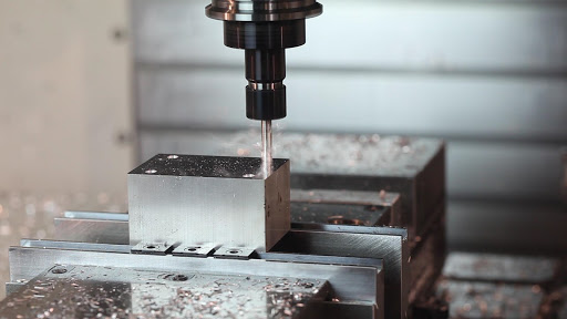
Drilling refers to the operation of creating holes in a piece of material. Drilling tools are designed for vertical cutting and have a conical tip, allowing them to plunge deep into a material.
However, drill too deep and you start running into problems. The maximum depth of drilling should be 12 times the nearest bit diameter. Drill bits at this length or longer decrease the stiffness and ability to keep to a tight tolerance, as well as increasing the chance of the bit breaking. If you do need to go deeper, consider increasing the hole diameter. Another option is to drill from both sides of the part if it is completely necessary to have such a deep hole. Keep in mind that this will add time and cost to the manufacturing process due to the need for an additional machining setup.
Through Holes vs Blind Holes
A through hole goes through the entire part, whereas a blind hole does not. Through holes have the benefit of being easier to clean out and are better for cooling. Reaming and threading are also easier to do with through holes. However, through holes can conflict with functional requirements, for instance on the external shell of a vacuum-sealed chamber.
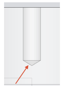
Keep in mind that when drilling a blind hole, the conical tip on a drill bit will leave a drill point that will not count towards the length of your hole, especially when threading. Make sure that the depth of the hole above the drill tip is sufficient for the mating part or thread engagement.
If you need to drill a blind hole, design it to be 25% longer than the necessary depth. This will allow room for chips that may collect and account for the conical tip.
Avoid Partial Holes
Partial holes should be avoided because there is a high chance of tip wander. If you do need a partial hole, keep the drill axis on the material so the majority of the hole is contained in the part.
Keep Drill Axis Perpendicular to the Surface
The drill axis should be perpendicular to the surface so that tip wander does not occur. In a lot of cases, a shallow, flat bottomed pocket can be milled onto the surface of a round part so that the drill enters perpendicular to the surface. A pilot hole can also be used, although this decision would be made when programming the CNC machine rather than during design of the part.
Avoid Drilling Through Cavities
Design the locations of your drilled holes so they are not intersecting with an existing cavity in the part. If it is completely unavoidable, the drilled hole can intersect slightly with the cavity, as long as the center axis of the hole does not intersect with the cavity.
Use Standard Drill Sizes
Use standard drill sizes. This can be applied to all cutting operations: designing your part to be cut by standard, common tools will save you lots of money! Machine shops can create new tools of unusual size, but this is a costly process and chances are you can tolerate a standard .125” hole instead of a .123” hole.
Similarly, if you have multiple holes in your part, try to minimize the number of different drill sizes. Obviously, there will be cases where you absolutely need different sized-holes, but if they are relatively close, see if you can pick one size. This will reduce the amount of time spent on tool changes.
STANDARD THREAD SIZE (METRIC)
| THREAD SIZE | TAP DRILL HOLE SIZE FOR SOFT METALS* AND PLASTICS (MM) | TAP DRILL HOLE SIZE FOR HARD METALS** (MM) | MAX TAP DEPTH (MM) |
| M1x0.25 | 0.75 | 0.85 | 9.53 |
| M1.2×0.25 | 0.95 | 1.00 | 9.53 |
| M1.4×0.3 | 1.10 | 1.20 | 5.16 |
| M1.5×0.35 | 1.15 | 1.25 | 5.16 |
| M1.6×0.35 | 1.25 | 1.35 | 7.94 |
| M1.8×0.35 | 1.45 | 1.55 | 9.53 |
| M2x0.45 | 1.55 | 1.70 | 11.11 |
| M2x0.4 | 1.60 | 1.75 | 11.11 |
| M2.2×0.45 | 1.75 | 1.90 | 11.11 |
| M2.5×0.45 | 2.05 | 2.20 | 12.70 |
| M3x0.6 | 2.40 | 2.60 | 15.88 |
| M3x0.5 | 2.50 | 2.70 | 15.88 |
| M3.5×0.6 | 2.90 | 3.10 | 17.46 |
| M4x0.75 | 3.25 | 3.50 | 19.05 |
| M4x0.7 | 3.30 | 3.50 | 19.05 |
| M4.5×0.75 | 3.70 | 4.00 | 22.23 |
| M5x1.0 | 4.00 | 4.40 | 22.23 |
| M5x0.9 | 4.10 | 4.40 | 22.23 |
| M5x0.8 | 4.20 | 4.50 | 22.23 |
| M5.5×0.9 | 4.60 | 4.90 | 22.23 |
| M6x1.0 | 5.00 | 5.40 | 25.40 |
| M6x0.75 | 5.25 | 5.50 | 25.40 |
| M7x1.0 | 6.00 | 6.40 | 28.58 |
| M7x0.75 | 6.20 | 6.50 | 28.58 |
| M8x1.25 | 6.80 | 7.20 | 28.58 |
| M8x1.0 | 7.00 | 7.40 | 28.58 |
| M9x1.25 | 7.80 | 8.20 | 31.75 |
| M9x1.0 | 8.00 | 8.40 | 31.75 |
| M10x1.5 | 8.50 | 9.00 | 31.75 |
| M10x1.25 | 8.80 | 9.20 | 31.75 |
| M10x1.0 | 9.00 | 9.40 | 31.75 |
| M11x1.5 | 9.50 | 10.00 | 42.07 |
| M12x1.75 | 10.30 | 10.90 | 42.07 |
| M12x1.5 | 10.50 | 11.00 | 42.07 |
| M12x1.25 | 10.80 | 11.20 | 42.07 |
| M14x2.0 | 12.10 | 12.70 | 42.07 |
| M14x1.5 | 12.50 | 13.00 | 42.07 |
| M14x1.25 | 12.80 | 13.20 | 42.07 |
| M15x1.5 | 13.50 | 14.00 | 42.07 |
| M16x2.0 | 14.00 | 14.75 | 46.04 |
| M16x1.5 | 14.50 | 15.00 | 46.04 |
| M17x1.5 | 15.50 | 16.00 | 46.04 |
| M18x2.5 | 15.50 | 16.50 | 46.04 |
| M18x2.0 | 16.00 | 16.75 | 46.04 |
| M18x1.5 | 16.50 | 17.00 | 46.04 |
| M19x2.5 | 16.50 | 17.50 | 46.04 |
| M20x2.5 | 17.50 | 18.50 | 50.80 |
| M20x2.0 | 18.00 | 18.50 | 50.80 |
| M20x1.5 | 18.50 | 19.00 | 50.80 |
| M20x1 | 19.00 | 19.00 | 50.80 |
| M22 x 1 | 21.00 | 21.00 | 55.00 |
| M22 x 1.5 | 20.50 | 20.50 | 55.00 |
| M22 x 2 | 20.00 | 20.00 | 55.00 |
| M22 x 2.5 | 19.50 | 19.50 | 55.00 |
| M24 x 1.5 | 22.50 | 22.50 | 60.00 |
| M24 x 2 | 22.00 | 22.00 | 60.00 |
| M24 x 3 | 21.00 | 21.00 | 60.00 |
** Hard metals include Steel 1018 and all Stainless steels
STANDARD THREAD SIZE (IMPERIAL)
| THREAD SIZE | TAP DRILL HOLE SIZE FOR SOFT METALS* AND PLASTICS (MM) | TAP DRILL HOLE SIZE FOR HARD METALS** (MM) | MAX TAP DEPTH (MM) |
| 0-80 | 1.19 | 1.32 | 7.94 |
| 1-64 | 1.51 | 1.59 | 9.53 |
| 1-72 | 1.51 | 1.61 | 9.53 |
| 2-56 | 1.78 | 1.85 | 11.11 |
| 2-64 | 1.78 | 1.93 | 11.11 |
| 3-48 | 1.99 | 2.18 | 12.70 |
| 3-56 | 2.08 | 2.26 | 12.70 |
| 4-40 | 2.26 | 2.44 | 14.29 |
| 4-48 | 2.37 | 2.49 | 14.29 |
| 5-40 | 2.58 | 2.78 | 15.88 |
| 5-44 | 2.64 | 2.79 | 15.88 |
| 6-32 | 2.71 | 2.95 | 17.46 |
| 6-40 | 2.87 | 3.05 | 17.46 |
| 8-32 | 3.45 | 3.66 | 19.05 |
| 8-36 | 3.45 | 3.73 | 19.05 |
| 10-24 | 3.80 | 4.09 | 22.23 |
| 10-32 | 4.04 | 4.31 | 22.23 |
| 12-24 | 4.50 | 4.80 | 23.81 |
| 12-28 | 4.62 | 4.91 | 23.81 |
| 12-32 | 4.70 | 4.98 | 23.81 |
| 1/4-20 | 5.11 | 5.56 | 25.40 |
| 1/4-28 | 5.41 | 5.79 | 25.40 |
| 1/4-32 | 5.56 | 5.79 | 25.40 |
| 5/16-18 | 6.53 | 7.04 | 28.58 |
| 5/16-24 | 6.91 | 7.14 | 28.58 |
| 5/16-32 | 7.14 | 7.37 | 28.58 |
| 3/8-16 | 7.94 | 8.43 | 31.75 |
| 3/8-24 | 8.43 | 8.84 | 31.75 |
| 3/8-32 | 8.73 | 9.09 | 31.75 |
| 7/16-14 | 9.35 | 9.92 | 36.51 |
| 7/16-20 | 9.92 | 10.32 | 36.51 |
| 7/16-28 | 10.26 | 10.49 | 36.51 |
| 1/2-13 | 10.72 | 11.51 | 42.07 |
| 1/2-20 | 11.51 | 11.91 | 42.07 |
| 1/2-28 | 11.91 | 11.91 | 42.07 |
| 9/16-12 | 12.30 | 13.10 | 42.07 |
| 9/16-18 | 13.10 | 13.49 | 42.07 |
| 9/16-24 | 13.10 | 13.49 | 42.07 |
| 5/8-11 | 13.49 | 14.29 | 46.04 |
| 5/8-18 | 14.68 | 15.08 | 46.04 |
| 5/8-24 | 14.68 | 15.08 | 46.04 |
| 11/16-24 | 16.27 | 16.67 | 46.04 |
| 3/4-10 | 16.67 | 17.46 | 50.80 |
| 3/4-16 | 17.46 | 17.86 | 50.80 |
| 3/4-20 | 17.86 | 18.26 | 50.80 |
| 13/16-20 | 19.45 | 19.84 | 50.80 |
| 7/8-9 | 19.45 | 20.24 | 56.36 |
| 7/8-14 | 20.64 | 21.03 | 56.36 |
| 7/8-20 | 21.03 | 21.43 | 56.36 |
| 15/16-20 | 22.62 | 23.02 | 56.36 |
| 1″-8 | 22.23 | 23.42 | 63.50 |
| 1″-12 | 23.41 | 24.21 | 63.50 |
| 1″-20 | 24.21 | 24.61 | 63.50 |
** Hard metals include Steel 1018 and all Stainless steels
STANDARD THREAD SIZE (NPT)
| THREAD SIZE | TAP DRILL HOLE SIZE (MM) | MAX TAP DEPTH (MM) |
| 1/16″ NPT | 6.15 | 17.46 |
| 1/8″ NPT | 8.43 | 19.05 |
| 1/4″ NPT | 11.11 | 26.99 |
| 3/8″ NPT | 14.29 | 26.99 |
| 1/2″ NPT | 17.86 | 34.93 |
| 3/4″ NPT | 23.02 | 34.93 |
| 1″ NPT | 28.97 | 44.45 |
STANDARD THREAD SIZE (NPS)
| THREAD SIZE | TAP DRILL HOLE SIZE (MM) | MAX TAP DEPTH (MM) |
| 1/8″ NPS | 9.09 | 19.05 |
| 1/4″ NPS | 11.91 | 26.99 |
| 3/8″ NPS | 15.08 | 26.99 |
| 1/2″ NPS | 19.00 | 34.93 |
| 3/4″ NPS | 24.21 | 34.93 |
| 1″ NPS | 30.56 | 44.45 |
| 1/8″ NPS | 9.09 | 19.05 |
Threaded Holes
Threaded holes should have between 1-1.5D thread engagement. For instance, a 1⁄4-20 machine screw should have a thread engagement between .25” and .375”. Depending on the application of your product, you may want even more thread engagement, but 1.5D is comfy.
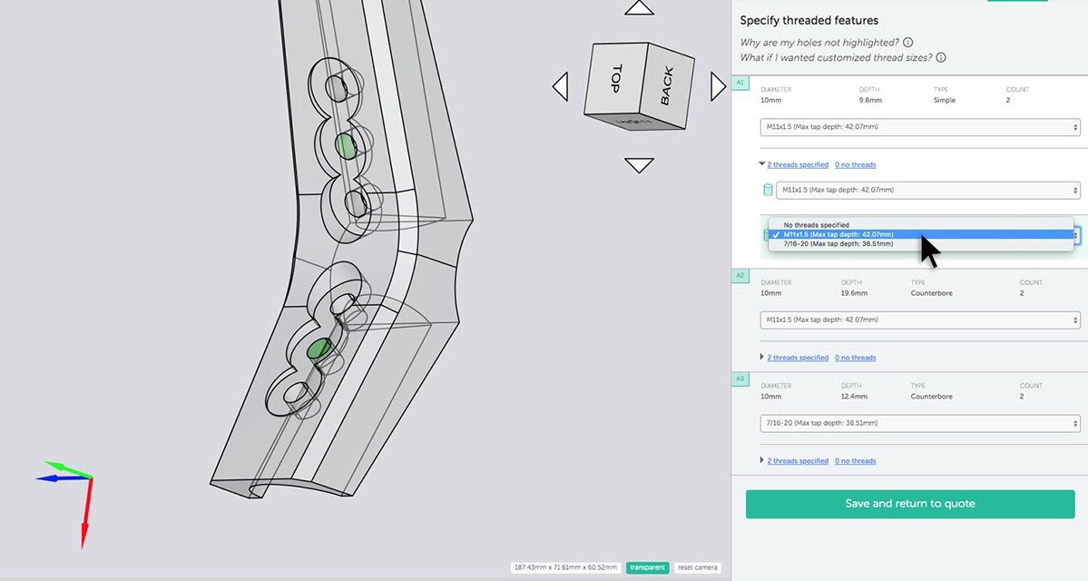
The China Manufacturing parts, Inc. platform makes it easy to specify threaded holes in designs for CNC machining with our Auto Thread Detection feature.
Custom Holes
For threaded holes with custom dimensions, you can easily upload a 2D drawing to the platform instead of using the Auto Thread Detection feature.
Whenever possible, threaded holes should be designed to standard thread sizes. A hole with non-standard threading will increase cost and lead time as the manufacturer will have to source a different thread former or cutting tool. Additionally, they may not have a way to check the non-standard threading, adding risk to your part.
Avoid Deep Taps
Deep taps should be avoided because long tools have a tendency to vibrate and wander, resulting in a flawed tap. The longer the tap, more likely it is that the tap will break or create threads that are not perfect or ideal. A deep tap would be one that goes further than 3 times the diameter of the tap. Even this deep of a tap is not always necessary, as 1.5 times the diameter will provide enough thread engagement.
CNC Milling
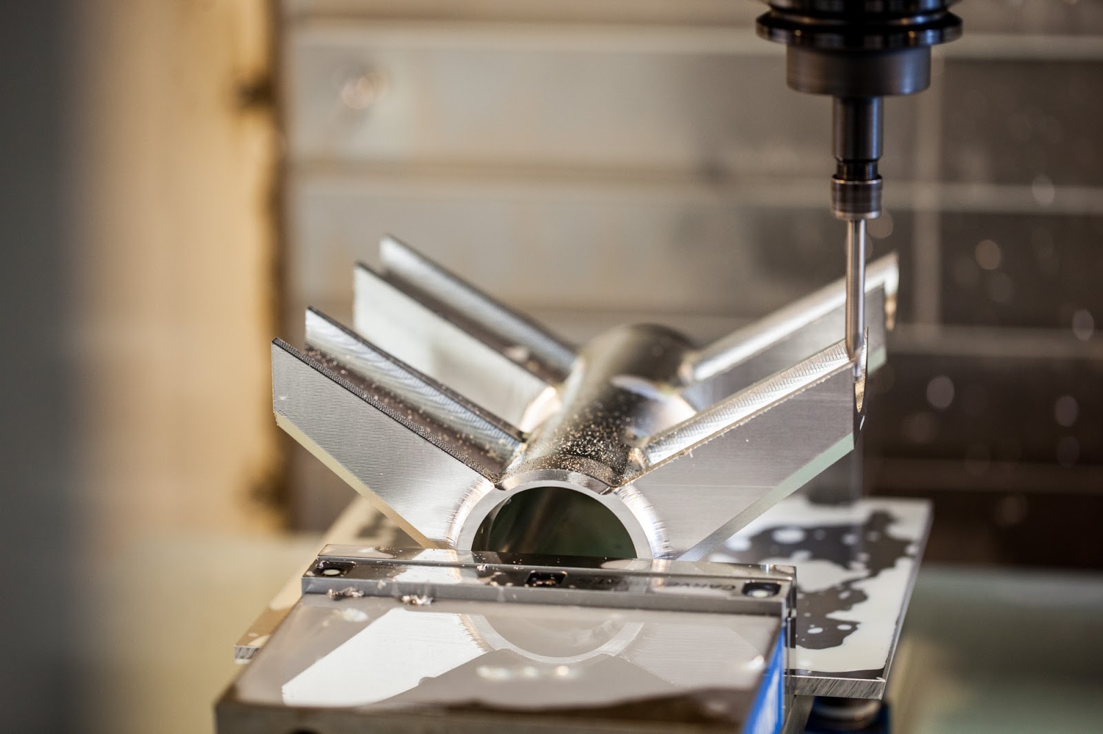
CNC milling refers to the machining process of quickly subtracting material from raw stock until the desired shape is achieved. Milling is performed by round cutters (most commonly end mills) which chip away material laterally with shallow depths of cut. There are many different configurations of CNC mills from 3-axis all the way up to 12-axis. In a 3-axis CNC milling machine, the stock material is fixed in place, while the tool spins and moves up and down to remove material. The bed of the machine then moves side to side, and back to front. For more on what CNC machines can do beyond 3 axes, check out this article.
Commonly Available Cutting Tools
When designing your part, keep in mind the types of tools that are commonly available for CNC milling. If you are able to achieve the features and geometry you need with standard tools, you can reduce cost and lead time. Otherwise, the manufacturer will have to spend time and money sourcing or making specialty tools. Below are some tools that are commonly available in machine shops.
These standard tools also have standard sizes. Like drills and taps mentioned above, you want to design to these standard sizes as much as possible. For instance, with internal fillets, you don’t want to design them to have a radius that is slightly smaller than that of a standard cutting tool. This would require a tool change to a smaller tool just to achieve that one, probably unimportant, feature.
Avoid Sharp Internal Corners
Because milling is done with round tools, sharp internal corners cannot be achieved. Radiused corners are required, and must be larger than the cutter to be used. The radius of the corner will be half the diameter of the cutting tool. For instance, a 1⁄4 ” cutter can be used for fillets larger than 1/8”.
If another part with sharp corners needs to fit inside the cavity, the corners can be “broken” by drilling a hole. This opens them up, allowing sharp corners to fit inside.
Fillets are also necessary when a drafted or sloped surface meets a vertical wall or sharp edge. A square or ball end mill will always leave material between the wall and the surface below, unless that surface is perfectly flat and normal to the tool.
Avoid Deep, Narrow Slots
The final depth of cut of an endmill should be not greater than 15 times the diameter for plastics, 10 times the diameter for aluminum, and 5 times the diameter for steel.
This is because long tools tend to deflect and vibrate, resulting in bad surface finishes. For example, a slot for a machined steel part that is .55” wide (which will be cut using a .5” endmill) should be no deeper than 2.75”. Internal fillet radius, the above point, is also dependent on this tool diameter, meaning that any internal radii for this example should be greater than .25”. End mills with a high length to diameter ratio are also more difficult to source.
If you can, either decrease the depth of the slot or feature, or increase the diameter of the cutting tool (which may require increasing the width of the feature. If it is possible to reach the feature from two directions, reducing the necessary length of the tool, this could work. However, this will require an additional machining setup and will add to the cost and time of machining.
Design with the Largest Possible Internal Radii
The larger the cutter, the more material can be removed at one time, meaning less machining time and less cost. Always design with the largest allowable internal radii. Avoid radii less than 0.8mm whenever possible.Pro Tip: Make your fillets slightly larger than the radius of the endmill, for example, a radius of .130” (3.3mm) instead of .125” (3.175mm). This will produce a smoother path for the mill to take, resulting in a nicer finish.
Other Geometry
Thin walls on parts are difficult to machine – they create issues with stiffness and tolerances. The thickness of a wall should be kept above 0.25mm for metals and 0.50mm for plastics in order to hold up to the manufacturing process.
On a related note, removing too much material from a part will put a lot of stress on the material. This may cause the material to warp or deform, changing the dimensions from what is intended.
In general, you want to make sure that the tool can reach the features on your part. Check that there are no other features in the way and that you won’t need an extra long tool to reach inside a deep cavity.
CNC Turning
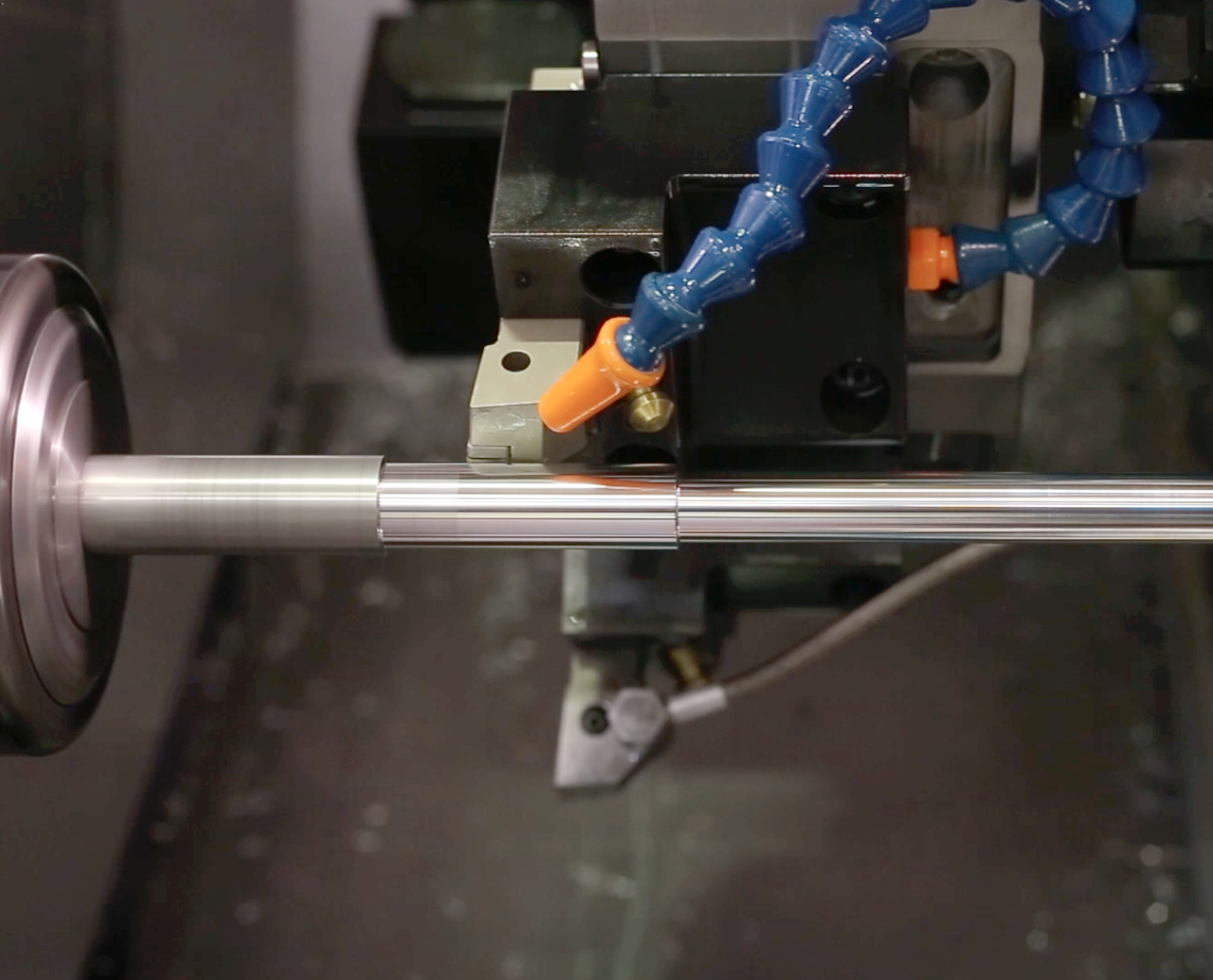
CNC turning refers to parts created on a lathe, generally with cylindrical geometry and axial symmetry. The stock material is held in a chuck, which rotates, while a cutting tool moves up and down and side to side to remove material. Turning has the benefits of holding tight tolerances and can provide a nice surface finish.
Avoid Sharp Internal corners
Avoid sharp corners, both internal and external. Internal corners should be radiused so that the tool doesn’t run up to a large surface. Another way to avoid sharp internal corners is to relieve a steep sidewall to give it a slight angle (as shown below). This can make it easier to machine contours with a single tool, reducing the number of operations necessary.
Avoid Long, Thin Parts
Avoid long, thin turned parts as there is more of a chance of them spinning unstably, causing them to chatter against the tool. If a long part must be made, try to accommodate a center drill on the free end and use a center to keep the part spinning straight. A good rule of thumb is to keep the ratio of the length to diameter 8:1 or less.
Avoid Thin Walls
As with milling, machining away too much material can result in undue stress in the part. Walls that are too thin will also decrease the stiffness. This will make it difficult to maintain tight tolerances. Wall thickness on turned parts should be kept above 0.02 inches.
Feature Symmetry
In general, any feature that is added to a turned part should be symmetric about the turn axis. Adding any geometry or features that are not axially symmetric will require more complex machining and setups. Features that are great for turning include steps, tapers, chamfers, and contours.
Sometimes, you may need to add features to a turned part that are not axially symmetric, and may require another operation. When this is necessary, you can still maintain an element of symmetry. If you are adding a slot or keyway, for instance, it should be centered on the axis, as shown in the image below.
Advanced Tips
Once you have a good understanding of the design practices we’ve covered so far, you can start to apply the following advanced tips to really solidify your lean design process. The first few tips are about increasing the speed of machining and minimizing the start-to-finish fabrication time, thereby reducing cost.
Create Easy Setups
Create easy setups for your machine shop. Think about how your part will be held during the machining process. The easiest setup is a vise, meaning your part will have straight, parallel outer edges. Curved edges (other than perfect cylindrical profiles) require custom fixtures, costing extra time and money. Thin parts are difficult to hold and are prone to warping. Parts are also easier to set up and machine if all features can be reached by the tool in just one orientation. Otherwise, the part will need to be rotated mid-operation.
Harder Materials = Increased Machine Time
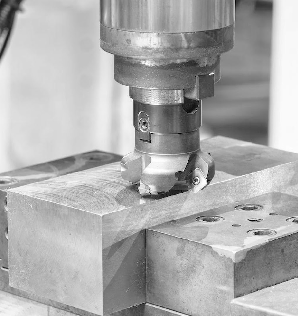
Steel, Stainless Steel, and other hard materials are also slow to machine. Materials like this exponentially increase the time required to machine because every operation is slower. Substituting a strong, softer material like 6061 Aluminum can save you a lot of time and money in the long run.
Non-standard materials can also be more difficult to source and may add to the lead time and cost in that way. It is also good to make sure that the material you want to use is available in a stock size that makes sense for your part. If your part is larger than the stock size of that material, either that will make it impossible to machine or add a significant amount of effort to source or create material that is large enough.
Similarly, if you have a small part to machine, but the smallest stock material is much larger than your part, you will waste time machining away unnecessary material and money paying for that wasted material.
Non-planar and Draft Angle Surfaces Increase Cost
Non-planar and draft angle surfaces are slow to machine, resulting in more time per part on the CNC machine, and more cost. If you think about a cutting tool as having directions of material removal, the most efficient ways to machine are in line with those vectors. Contouring or surfacing, which are not require your tool to either be at a weird angle to your part or many multiples of passes to create a smooth surface, will add to the lead time and cost of your part.
Minimize Operations
Tool Changes
A tool change is when the CNC machine swaps out cutting tools for a new operation. If you can minimize these tool changes, it will cut down on production time. One example of this is using the same hole size or internal corner radius wherever you can.
Workholding Setups
Similarly, every time you need to change the orientation of a part or the way that it is fixtured in a machine, you add time and therefore cost to the manufacturing process. Read more about different workholding options that can decrease your manufacturing effort.
Inside Fillets vs Chamfers
Inside chamfers are time consuming and difficult to create. Inside fillets are easier to make because round tipped end mills can be used.
Pro Tip: Place a note on your drawing saying “break all edges” instead of building lots of tiny chamfers on your modeled part. China Manufacturing parts, Inc. will break sharp edges unless otherwise instructed by the customer.
Tolerances and GD&T
Paying careful attention to your tolerances and GD&T as you design your part is important for CNC machining. Unnecessarily tight tolerances can greatly increase the time and cost of the machining process. For example, tolerances tighter than 0.05mm (0.002”) might be loosened by your manufacturer.
Certain materials are particularly difficult to hold to tight tolerances. For example, when machining plastic, the temperature can vary and have adverse effects on the material. These effects can include warping, chips gumming up the tool, and poor surface finish. Therefore, tolerances below 0.1mm (0.004”) are difficult to hold and should be loosened. If such tight tolerances are necessary, PEEK is a plastic that can stand up to high temperatures.
To further advance your design for CNC machining skills, check out our DFM for CNC Machining Master Class. You can also learn more about China Manufacturing parts’s CNC machining capabilities here and create your free China Manufacturing parts, Inc. account to upload your designs and get automated DFM feedback.