Time to read: 4 min
One of the most advantageous mechanical gearing systems is the strain wave gear, also known as a harmonic drive. It has high gear reduction ratios (ranging from 30:1 to 320:1), which allow for high speed reduction, no backlash, and high torque, all in a compact and lightweight system. Because of these abilities, the system is often used in robotics, aerospace, and manufacturing. Although very useful, the strain wave gear is difficult to 3D print because of its complicated parts. Let’s explore which 3D printing processes and materials are most suitable for creating a strain wave gear, including its important characteristics.
What is a Strain Wave Gear?
A conventional strain wave gear is made up of 3 different parts: the circular spine, flexspline, and the wave generator. These parts, each with a different function, combine to create an efficient speed reducing gear system.
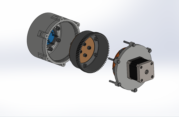
The wave generator is what creates the movement in the harmonic drive. With an elliptical-shaped disk, this piece rotates to move the flexspline that surrounds it. While its designs vary, it usually consists of an outer ball bearing.
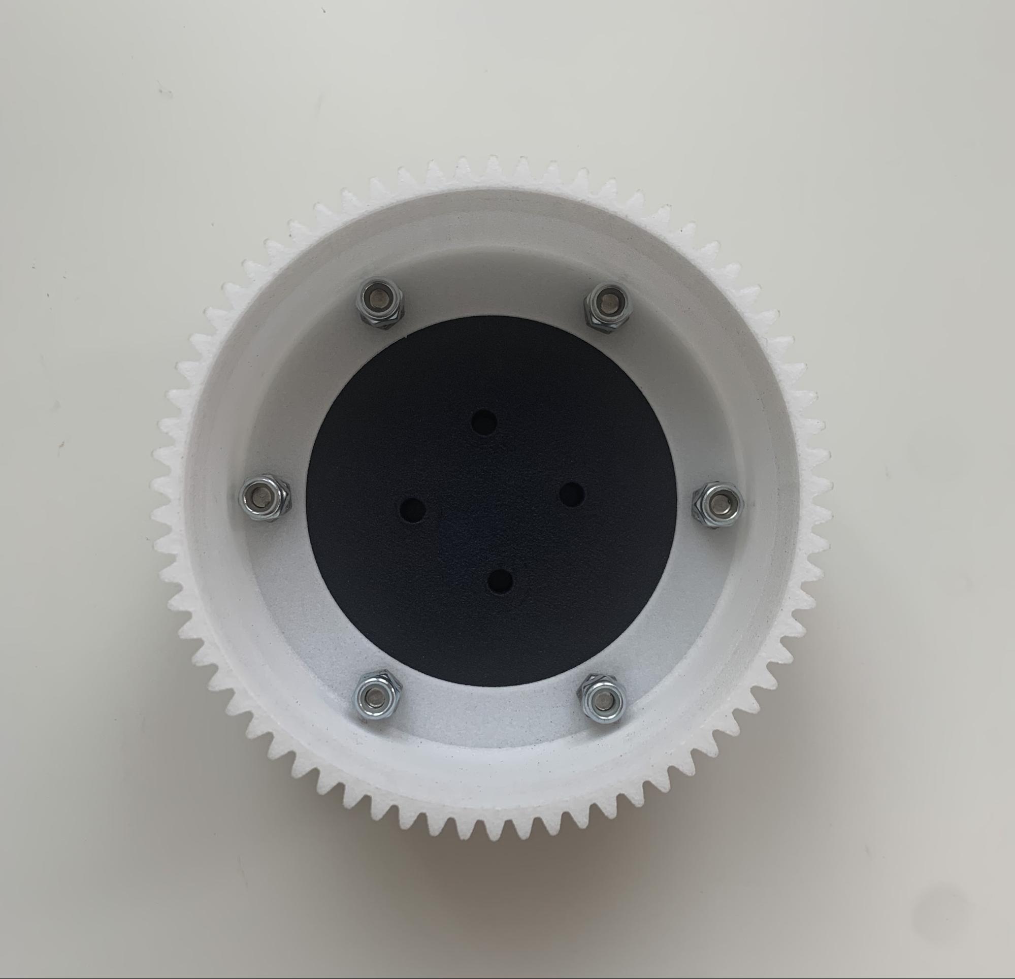
The flexspline, the focus of this project, is the shape of a cup, with gears sitting on the outside edge of the open end. It is the key to the gear system working, as it has to be both flexible and rigid. Because of its elasticity, the flexspline contours to the shape of the wave generator, and as it rotates, it moves over the gears of the circular spline.
The circular spline is like the flexspline, but larger, because it is the outer piece of the gear system. A crucial requirement of the circular spline is for it to have two more gear teeth than the flexspline. It also has the gear teeth on the inside of the open end, so that they come in contact with those from the flexspline.
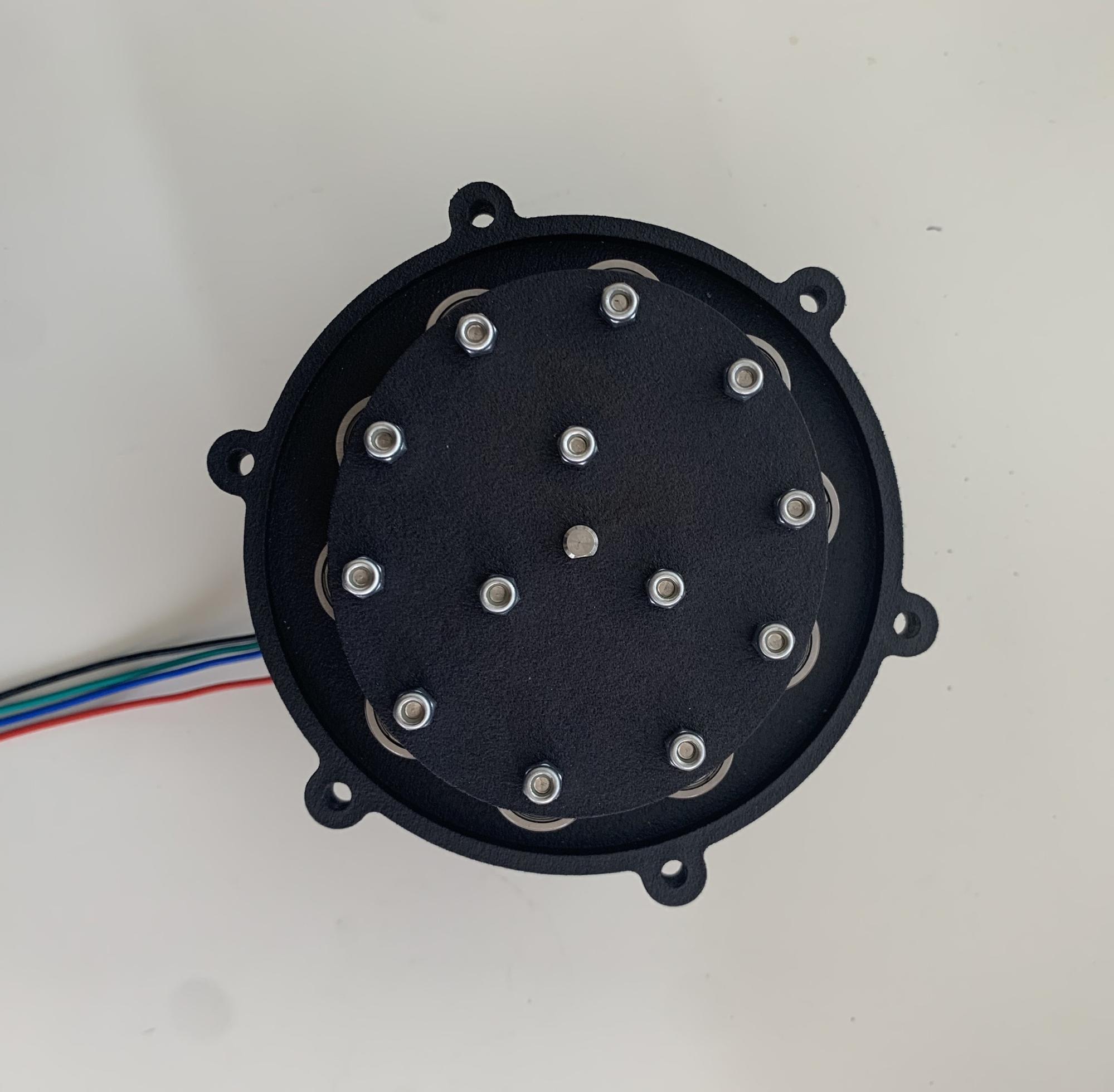
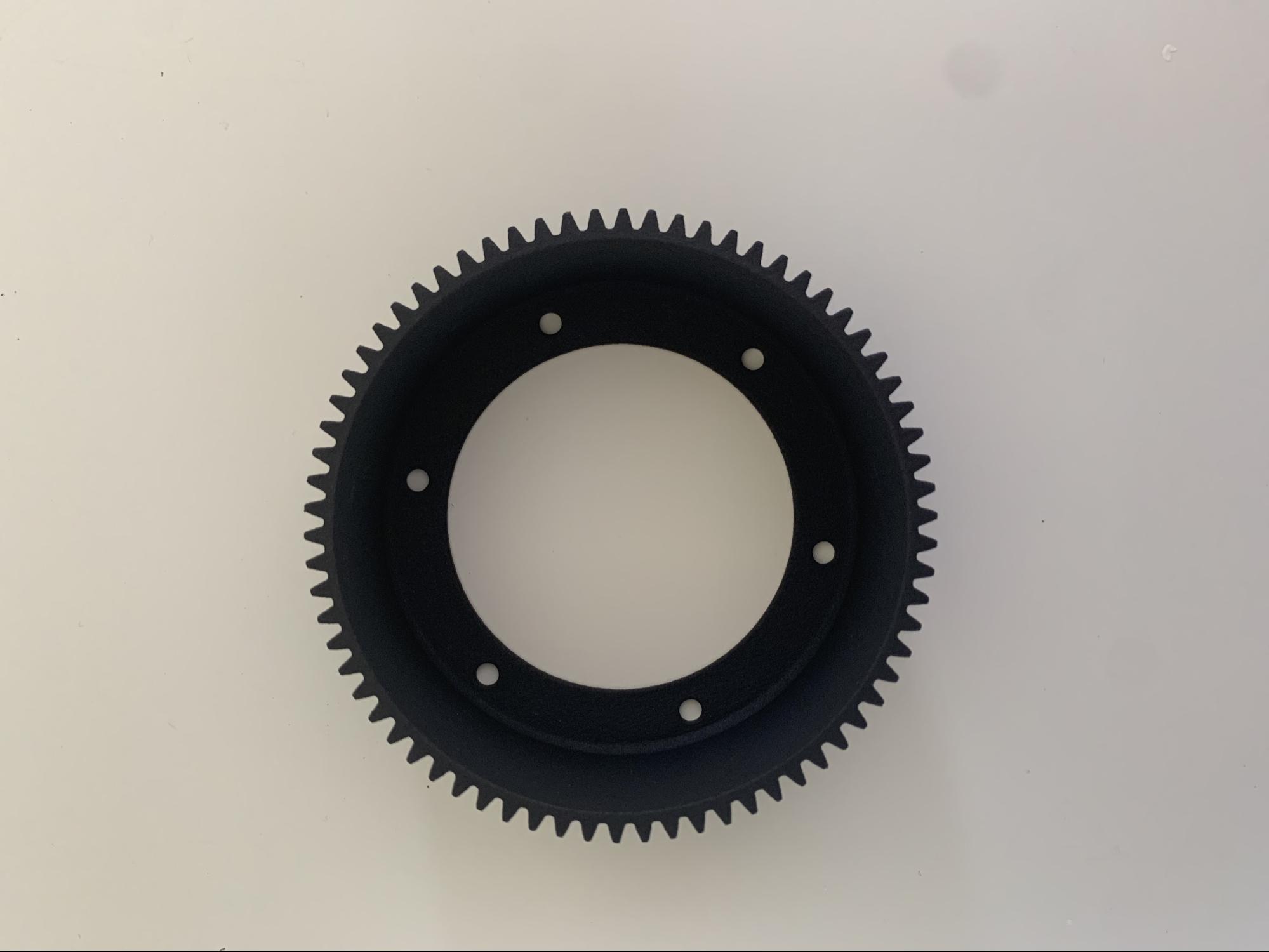
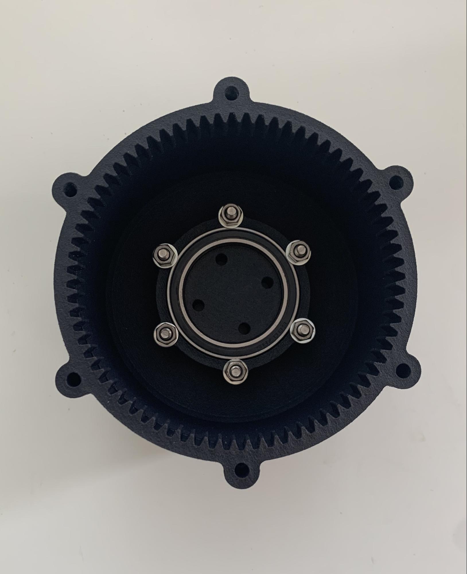
With these three parts, the strain wave gear can work efficiently. As the wave generator rotates, it makes the flexspline mesh with the circular spline.
However, the gears only mesh completely in two diametrically opposed parts of the flexspline and circular splines. This is because the flexspline has two fewer gear teeth. By finding the reduction ratio, one can figure out the reduced speed at which the flexspline will rotate.
The Focus
Our particular focus is on the flexspline, which is a challenging piece for 3D printing. The vast majority of commercially available strain wave gearing systems are made from metal materials, such as alloy steel, so we had to choose materials that would make the flexspline both flexible on the sides and rigid at the gear teeth.
Many hobbyists have tried using desktop printers, with mixed results. Several have used off-the-shelf rubber drive belts for the flexspline. We wanted to test some of the traditional 3D printing materials and commercial technologies and some of the newer, more highly touted processes.
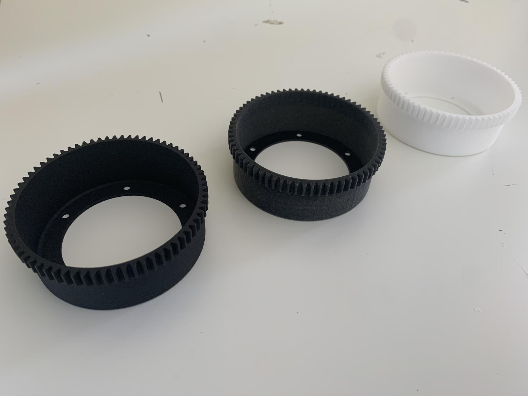
Our process consisted of testing three different flexsplines: a Multi Jet Fusion one, a Polyjet one, and a Selective Laser Sintering one. The rest of the harmonic drive parts were made from Multi Jet Fusion. It was assembled using off the shelf components and powered with a stepper motor. We tested it at low speeds (~100 rpm) and then at higher speeds (~500 rpm) to see how the flexsplines would perform.
Multi-Jet Fusion
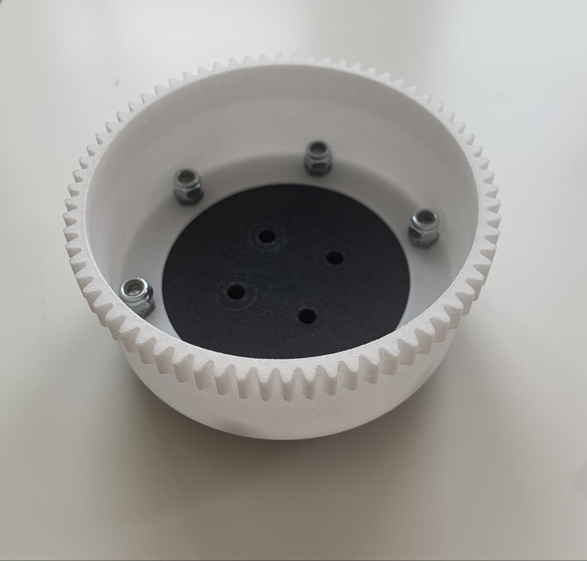
First, we tested the Multi Jet Fusion (MJF) flexspline. MJF is a newer technology and uses a nylon powder as the base material.
HP claims their tech is well suited for gear teeth. It looked great and had a smooth texture, which helped reduce friction.
Overall, it worked very well, both at low and high speeds. It has a bit of backlash, but that can be fixed in the actual design process. MJF is great, both very rigid and a bit elastic, making it a great 3D process for the flexspline.

Polyjet
Second, we tested the Polyjet process, using the rubber 90A shore hardness material, with the intention of replicating the results of an off the shelf rubber drive belt. That proved to be far more flexible than intended and lacking rigidity. This was not an issue at low speeds (below 100 rpm), and it worked relatively well.
But when the wave generator turned on at high speeds, the flexspline would start working then get stuck for a long time. This process may have been better suited if there was a hard plastic backing behind the gear teeth, but the material alone caused too much friction and was extremely flexible. While adjustments could be made to fix these issues and improve performance, the Polyjet flexspline was ineffective for this test trial.
Selective Laser Sintering
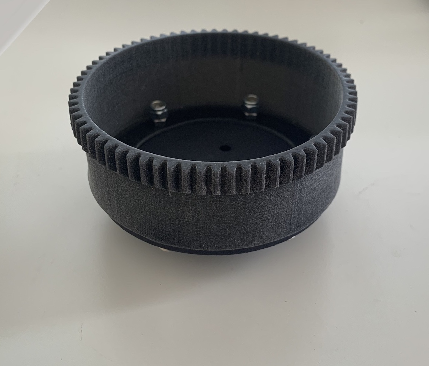
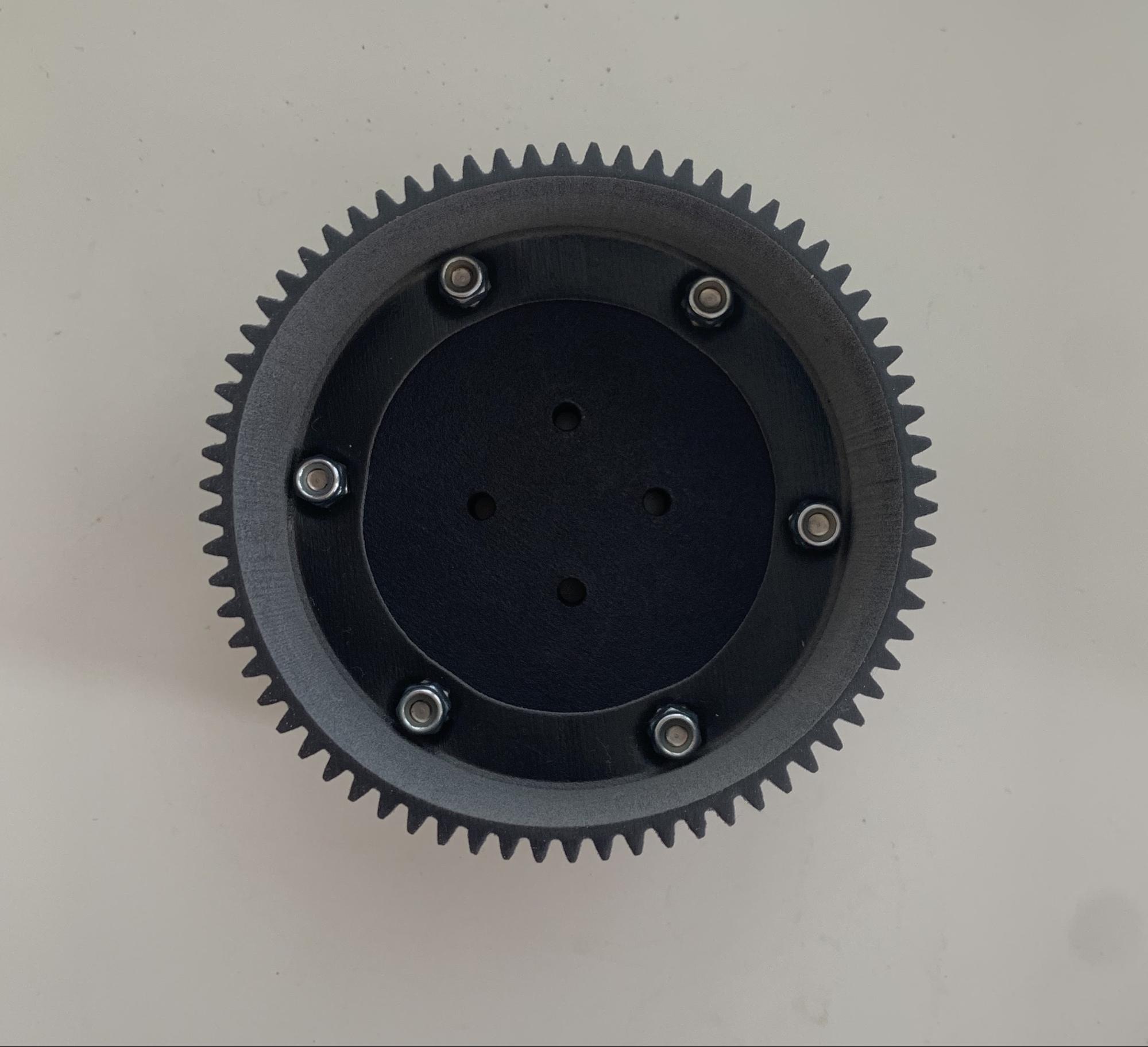
Third, we used a Selective Laser Sintering (SLS) flexspline made out of nylon. It was stiffer than both the previous materials, which ended up being the problem, in this case. Like the Polyjet, the SLS flexspline didn’t work well at high speeds (greater than 200 rpm). In fact, it didn’t work at all after it got stuck, but it was better than the Polyjet flexspline.
Main Takeaways
Multi Jet Fusion turned out to be the best process for a very rigid, yet slightly elastic material. It was great for the gear teeth, running the most smoothly out of all the flexsplines.
Polyjet was the most flexible, but flexibility was not the only thing we should’ve considered. While possibly useful for other applications, it isn’t practical for gear teeth without modifying the gear rigidity first.
The SLS flexspline was good for low speeds, but the material was inconvenient at higher speeds. Of course, these are only the results from our observations, but MJF is still highly recommended for gears if one doesn’t want to alter the material.


