Time to read: 8 min
So, you’ve been designing “things” using Solidworks for a while now. Maybe you took a Solidworks class or two, maybe you didn’t. Either way, you got to the point where you want to design more complicated & organic shapes and you are struggling. After all, designing organic shapes typically requires surface modeling in Solidworks, which they don’t teach in most classes and is notoriously difficult. Plus, people you know have told you that Solidworks is the wrong tool for surfacing.
Well, here is what you should know:
- Solidworks is an excellent 3D modeling program and is extremely versatile & user friendly.
- While Solidworks is not a surface modeling focused program, it has a wide array of extremely capable surfacing tools.
- Solidworks can be and is used to design amazing organically shaped products every day by both individuals at home and large corporations. It can be done. It is done.
- There are some limitations to the program, but that is to be expected of any software.
- The key to excelling at this or any other 3D modeling software is to understand the alleged “limitations” and know how to get around them.
- Practice makes perfect. Lots of practice makes more perfect!
Why Use Solidworks for Surface Modeling?
If you intend to surface model a lot, you might be asking yourself why you don’t just turn to a different CAD program that is more specialized for surface modeling. To answer that, I use the following analogy:
If you went to cook dinner in your kitchen and could only use ONE knife, which would you choose? Would you choose the small and nimble paring knife or the big butcher’s knife? You probably wouldn’t choose either one of them. After all, you can only have one knife. You would likely choose a medium size knife that works very well for most things, but you make sure it is razor sharp. It might not be ideal for small intricate cuts and it also might not be ideal for hacking away at a big block of meat. But, it can certainly do either. After some time, you begin to learn the best ways to get the most out of the medium size knife. After all, it can do everything you need it to.
I know this analogy doesn’t seem realistic at first considering that your kitchen probably has many knives to choose from. However, most people that design products using 3D software choose a single software and use it religiously for long periods of time. While you can learn multiple software programs and switch back and forth between them almost seamlessly, most designers stick with a particular software for many years at a time because most companies and certainly most individuals don’t budget for multiple software licenses. Don’t forget that professional 3D modeling software packages can get quite pricey. So, if you are going to have only one 3D modeling program, Solidworks is a great choice. It is the medium sized and extra sharp kitchen knife. With proper instruction and enough practice, it can do it all.
Tips & Tricks for Surface Modeling in Solidworks
Everything Doesn’t have to be Parametric
One of Solidworks’ well known benefits is the fact that you can 3D model parametrically. This basically means that you can change dimensions and/or shapes of existing features and sketches, click a button and watch Solidworks magically update the entire model. For most products and situations, that is an absolutely incredible and useful ability. However, just because you can 3D model things parametrically doesn’t mean that you always should.
There are plenty of shapes that you will end up creating that took so many features to create that you run a big risk of one feature creating an error that ruins the rest of the model. Plus, all of those features end up increasing your file size and wasting a lot of processing power each time the software has to regenerate the end result.
Once you end up with the geometry that you are happy with, you have three choices:
- Do nothing and hope that errors do not show up in your model the next time you reload the file or try to make changes
- Go back and rebuild the same end result in a way that uses fewer or more reliable steps
- Export the final geometry and then import it back into your model in a way that preserves the resulting shape, but removes all of the history of how you got to that resulting shape
For surface modeling of organic shapes, I most often choose the third option because I feel that reducing the risk of a part blowing up outweighs the benefits of the file being parametric. I believe this is especially true because parametric modeling is really only helpful if the changes you end up wanting to make are possible with the design strategy you used. If you try to make certain changes that you didn’t plan for from the beginning, you will likely have to rebuild some or all of your document anyway.
As a result, I often 3D model certain portions of a given design any way that I can using as many features as I need to and not caring how messy my feature tree becomes. Once I get to the end result I am hoping for, I do an error check on that surface or solid. If it passes inspection, I save the body out as a parasolid (*.X_T). Then, I use the import command (Insert -> Feature -> Imported) to import it back into the feature tree. I error check the imported geometry and if it passes inspection, only then do I delete all of the features that created it.
I suggest that you use this technique for aspects of your product, not the whole thing. Maybe you just want to cut the top off of your part using a complex surface. You can model the entire part parametrically and use a dumb surface as a cutting tool. In that case, everything would be parametric except for the one item that is most likely to cause problems if it were parametric. Remember, you can always replace the dumb surface you used as a cutter with a new one.
A few side notes:
- Export to parasolid (*.X_T) instead of IGES, STEP, etc because parasolids import back into SW with the fewest errors
- Select one or more bodies that you want to export and then click File -> Save As. After you select the file name, it will ask you if you want to save “All Bodies” or “Selected Body(ies)”. Choose “Selected Body(ies)” so you don’t have to export and then import unnecessary geometry.
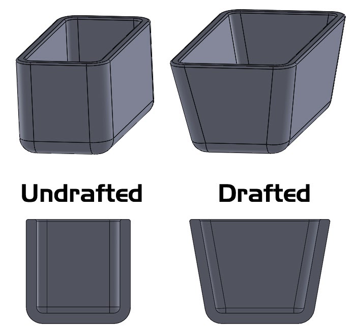
3D Modeling Drafted Surfaces
Many people struggle to properly add draft when they are surface modeling organically shaped molded parts. Draft is important for molded parts because it facilitates part removal from the mold once the part is molded.
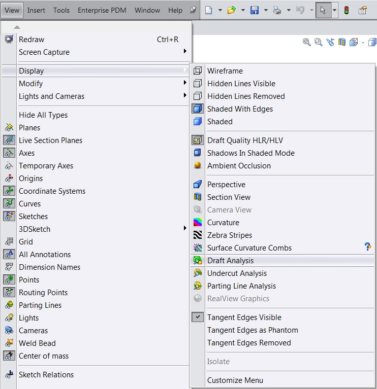
If you ever want to check a part’s draft, use the Draft Analysis tool (View -> Display -> Draft Analysis).
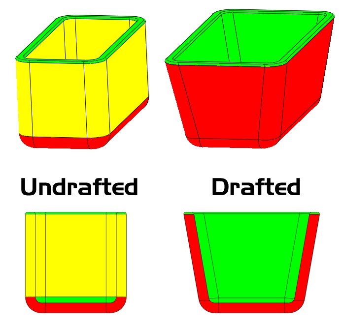
The Draft Analysis tool will color code your part as red, yellow and green based on a draft plane that you select and a draft angle you choose. Your goal should be to see only red and green, no yellow.
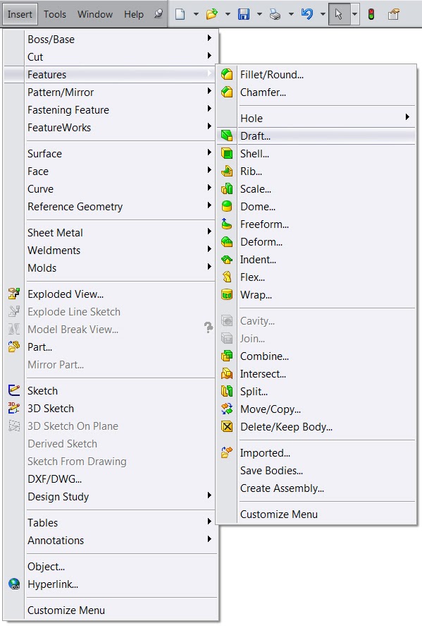
Here are 3 great ways to add draft your part:
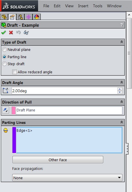
- Draft (Insert -> Feature -> Draft)
The Draft command is the most commonly used tool to draft existing geometry. This is the one they teach in most classes and the tool that you would expect to use. After all, it is called “Draft.” What you might not know about the Draft feature is that it works on surfaces as well.
I have found that the most useful setting for this feature is choosing “Parting Line” as your type of draft instead of “Neutral Plane”. This will allow you to choose an edge that will remain constrained to its current position while the adjoining face is drafted. That edge does not need to be flat, so this is incredibly helpful when designing organically shaped parts.
- Ruled Surface (Insert -> Surface -> Ruled Surface)
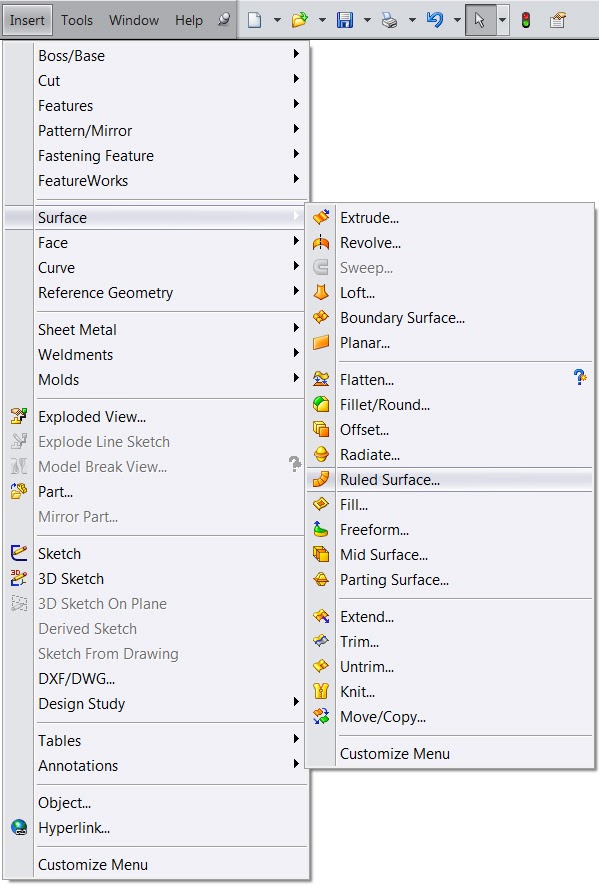
Ruled Surface is a great feature for creating drafted surfaces mostly from scratch. This feature will create a surface (not a solid), so this is very much a surface modeling feature. To use “Ruled Surface” to create a drafted surface, choose the “Tapered to Vector” option and choose your draft plane as the vector. Then, choose an edge to begin your new surface. Lastly, you get to choose which direction you want the surface to go as well as by how much, whether you want the surface drafted IN or OUT and by what angle.
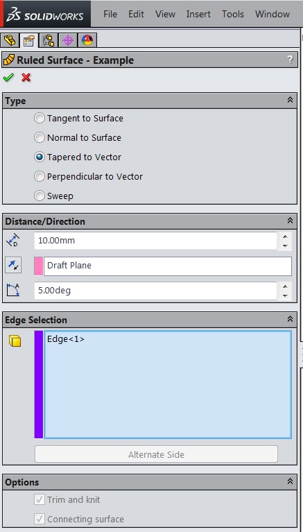
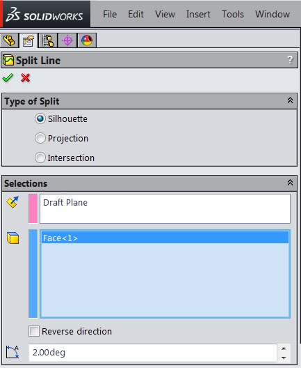
- Split Line (Insert -> Curve -> Split Line)
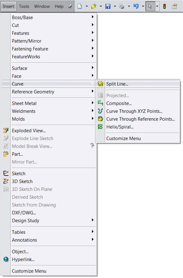
A lot of people don’t know that Split Line can be a very useful tool when drafting a part. If you select “Silhouette” as the type of split, you can choose a draft angle at the bottom. When you click ok, it will analyze the surface you selected and split it into two separate faces. One face will be in draft to the angle specified (or more) and the other will not. You can then use Ruled Surface or Draft to draft the undrafted face.
Summing it up
Solidworks is certainly not perfect. In fact, no 3D modeling software is. While Solidworks is not a surface modeling specific program, it is still quite adept at surfacing and can create virtually any product you can conceive of. The limitations of the program are worth the other benefits the software provides. Besides, with training and practice, you will find plenty of ways to work through any obstacle you come across.
So, get out there and get surfacing with Solidworks!
Additional Resources:
1. The Solidworks Advanced Part Modeling class and the Solidworks Surface Modeling class each provide excellent instruction in the more advanced fundamentals required for successful surface modeling. I suggest you take both of those classes OR get a hold of the books from those classes (likely from someone that did take the classes because the official books are not for sale). In either case, read both books and practice the examples from both of those books:
2. Solidworks is full of free tutorials, including several that involve surface modeling. Go through all of the tutorials and really play around with the settings and dimensions at each step to see how the result changes. The tutorials can be found by clicking on Help -> SOLIDWORKS Tutorials
4. Don’t forget to practice everything you learned on 3D models that are more relevant to what you already work on or to what you are interested in working on. This will make your time more enjoyable and you will get more out of it!
—
To get your 3D models printed in 24 hours, visit fictiv.com. In the meantime, check out the China Manufacturing parts Capabilities Guide.

