Time to read: 5 min
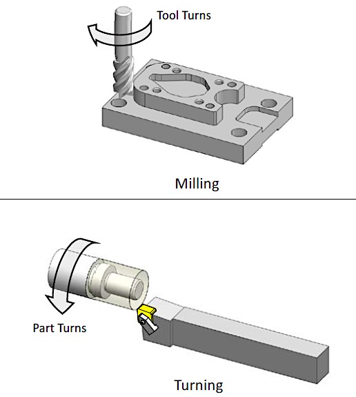
Previously, we discussed how CNC (Computer Numerical Control) supports manufacturing processes and reduces human error. We have also described CNC Milling, where the cutting tool moves while the workpiece is fixed in place. In this article, we‘ll explore CNC Turning, where the workpiece rotates while the cutting tool remains stationary.
CNC Lathes vs. CNC Turning Centers
If you’ve been around machine shops for very long, you’ve probably heard of both CNC Turning Centers and CNC Lathe Machines. You have probably heard them used interchangeably to describe what may seem to be the same manufacturing process performed by similar machines.
The first machines designed to cut a rotating workpiece were called lathes while turning referred to the cutting process in general. Before CNC technology, lathe machines were similar and easy to identify. However, with advancements in technology, new features have been added. So, there’s some need to differentiate between simpler machines that perform operations like the original lathes and enhanced machines that can perform turning cuts in additional ways.
Some companies differentiate based on the number of toolpath axes the machine can execute. CNC toolpaths can be classified as 2D, 3D, 4-axis, or 5-axis (this applies to both milling and turning cutting processes). Lathes generally are 2-axis machines, while turning centers are typically 3-axis, 4-axis, or 5-axis machines.
Other companies refer to machines that can perform turning cuts as well as milling and drilling operations as turning centers. To some extent, lathes and turning centers are interchangeable, so there’s no need to worry whether you call a machine a turning center or a lathe.
Turning basics
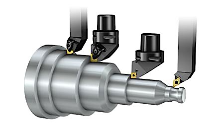
CNC turning starts with a rotating workpiece that’s usually cylindrical, but with the right adapter, different shapes can be used as stock material. The machine spins the workpiece while a tool moves to engage and remove material until the desired shape is achieved.
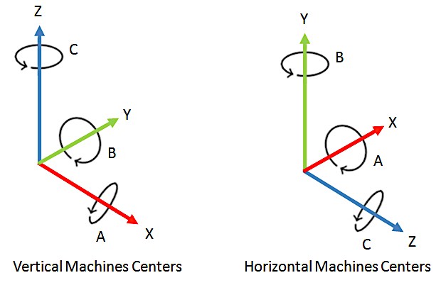
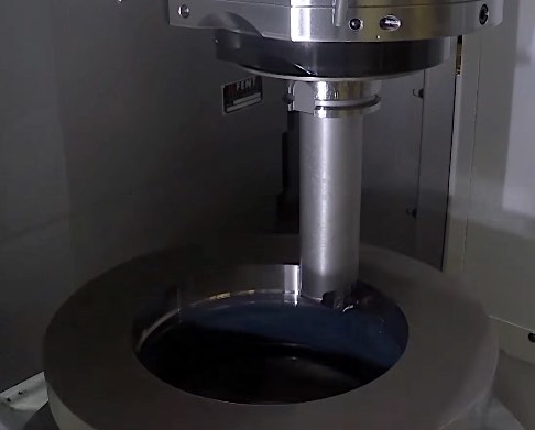
Turning machines can be vertical or horizontal, and the figure above shows the axes convention for vertical and for horizontal machines (6 axes shown). Vertical turning is typically used to machine large and heavy designs since horizontal turning supports the workpiece only on one end. That cantilever setup causes vibration in large, heavy pieces which affect the machining quality, and can damage the turning machine and tooling.
However, vertical turning has its drawbacks, especially when machining concave parts — the chips falling from the workpiece can become trapped inside the machine or fall into the spindle and cause problems. Horizontal machines don’t have that issue, which is partly why horizontal machines are more common, and their widespread use makes it easier to find trained operators.
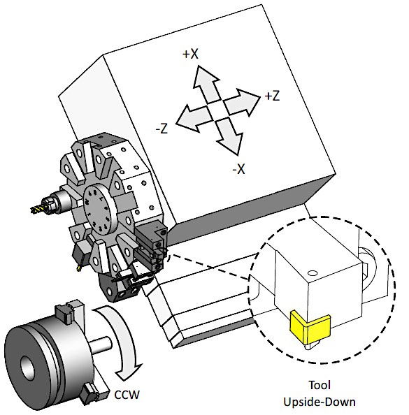
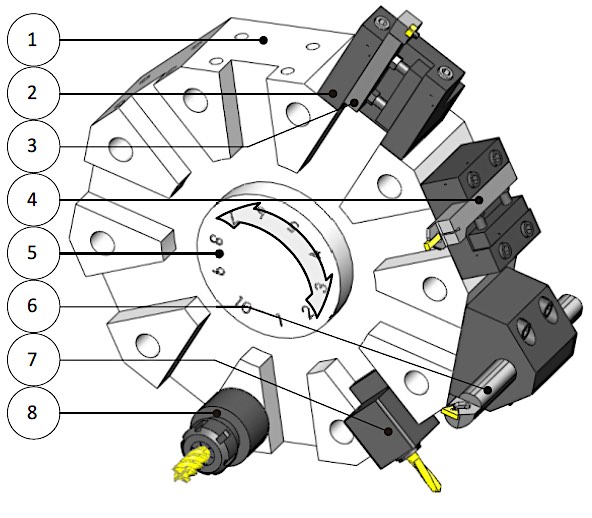
Some machines will have the turret (which holds the toolset and is detailed in the next section) set on an inclined plane. This configuration prevents formed chips from accumulating inside the turning machine during the cutting process.
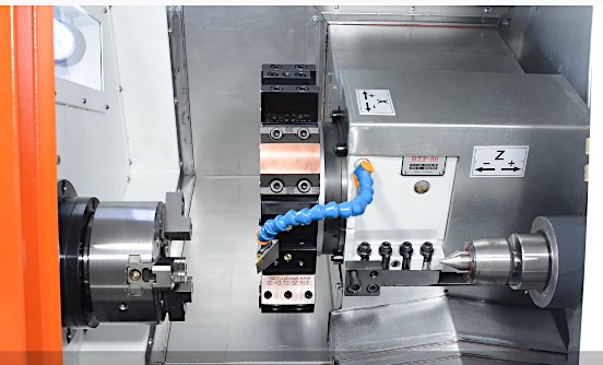
CNC Turning Machine Components
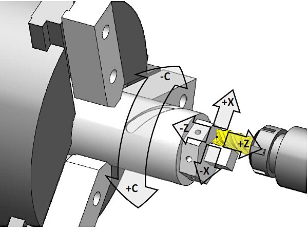
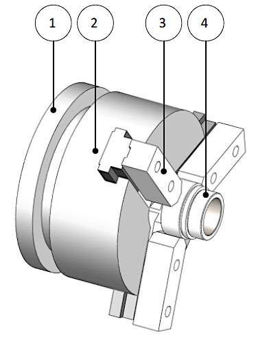
Turning machines are comprised of a spindle attached at one end to the machine drive system, while the other end attaches the chuck that grips the workpiece to be cut.
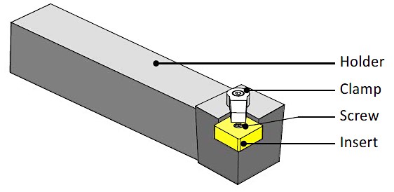
Cutting tools are often made of carbide inserts. Those inserts are gripped in tool holders, which are bolted to the turret using a variety of specialized holders, depending on the type of tool. Tools are then indexed as a part of the preparation before machining starts.
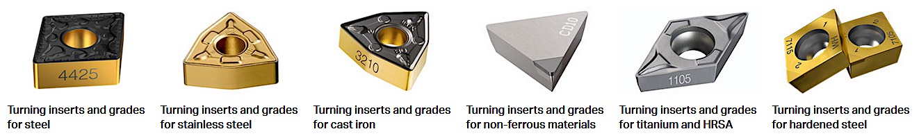
Several companies dedicate significant research efforts to designing better inserts, coatings, and new alloys to increase tool life and performance. Because there are a variety of insert designs, selecting the insert that’s appropriate for the workpiece material you are planning to machine is crucial. If you try to machine a hard material with a tool meant to machine softer materials, and you use the same values of speed and feed, you might break the tool or damage the workpiece.
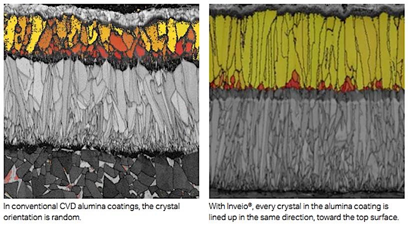
One key part of materials engineering for tool inserts is crystal orientation, so here’s a quick refresh on microstructure concepts. Using magnified photographs or digital images taken through a microscope, you can analyze the individual crystalline areas known as “grains” in a material. The structure, size, and orientation of these grains result from the material composition (alloy) and the way the material is made or modified by treatments and processes. These grain sizes and orientations are linked to mechanical properties.
Below you can see a comparison between the microstructure of a typical alumina coating for CNC turning inserts and the microstructure achieved with a technology from Sandvik called Inveio®. The typical coating has a random crystal structure, while Sandvik’s technology results in unidirectional crystals. This change in the microstructure improves crater wear and flank wear resistance, and improved heat transfer during machining. That helps the cutting edge stay in shape for longer and improves wear resistance and tool duration significantly to reduce machining costs.
Types of Turning Tools
Depending on your turning operations, different tools are best suited for the job. Below you’ll find descriptions of some of the most commonly used turning tools:
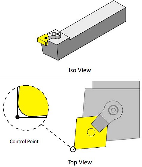
Face/Turning Tools
These are used to cut a flat surface perpendicular to the piece’s rotational axis. The tool is mounted into a tool holder that rests on the carriage of the lathe, during the process, the facing tool will feed perpendicularly across the rotational axis of the part. This type of tool is also used in rough turning (either for parts with flexible tolerances or for parts with tight tolerances requiring a first pass cut to remove a large amount of material before cutting with more precision).
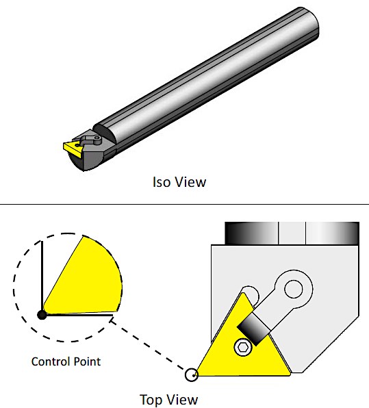
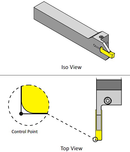
Boring Bars
A boring bar is used to increase the diameter of an existing hole.
Thread Cutters
Thread cutters are used to cut both internal and external threads on a workpiece.
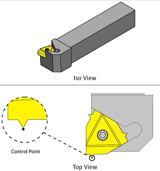
Grooving Tools
A grooving tool is typically used to create features like O-rings and contouring operations.
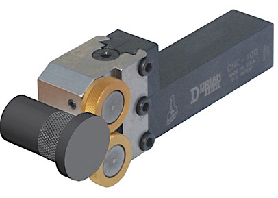
Knurling Tools
Knurling tools are designed with a specific pattern to produce grips on handles by pressing a pattern onto a round section of a part.
Of course, these five are only a few of the tools used for CNC Turning machines, but there are many more designed for a variety of operations.
Conclusion
Hopefully, this article has given you a better understanding of CNC Turning and how lathe machines work. With those capabilities in mind, it may prove to be the right manufacturing process for your next project. China Manufacturing parts provides a range of CNC turning and milling services, so create an account and upload your part today! Our in-house experts will provide you with free DFM feedback on your design to ensure that our manufacturing partners can produce the quality parts you need, fast.