Time to read: 7 min
Designing and building robots and other mechatronic designs has been simplified by the continued evolution of 3D printing technology, but it’s not without its challenges. 3D printed parts aren’t quite the same as their more expensive machined and molded cousins, and we need to take into account the tolerances, surface finishes, and other limitations of manufacturing. But it’s well worth it: Nothing is quite like bringing your own creation to life. So how do you go about designing parts for a 3D printed robot?
Robotics: Movement System Basics
On the mechanical side, robotics means movement systems: How do we get the robot to move an arm or a wheel? How will we translate the 6,000 rpm motor to a 10 rpm rotation of a carousel? The key, of course, is in gearing.
In all gears, the two primary things to think about are pitch and number of teeth. (Pressure angle should also be considered, but we’ll cover that in a little bit.)
Gear pitch refers to the size of the teeth. Imagine we have a 1” pitch diameter gear with 32 teeth—that becomes a 32-pitch gear. (Pitch diameter refers to the theoretical diameter of the gear that is the effective diameter for the lever arm of the gear, which means we use the pitch diameter for both calculating leverage between the forces gears transmit and also speed ratios.)
Similarly, in metric gearing, the module expresses the change in diameter per tooth: A 24mm diameter gear with 12 teeth is a module 2 gear. Only gears of the same pitch or module can work together.
The number of teeth tells us how much leverage we’ll get out of a pair of gears. If we have two 32-pitch gears, and the drive gear has 32 teeth, while the passive gear has 128 teeth, then the drive gear will spin four times for each rotation of the passive gear, and the passive gear will have approximately four times the torque (approximately, because friction will remove a little of the power).
Gearing for robotics development typically falls into one of four types, or combinations of these: spur gears, internal gears, worm gears, and rack and pinions. The first two of these will help you slow down—or speed up—rotary motion, while rack and pinion will translate that rotation into linear motion.
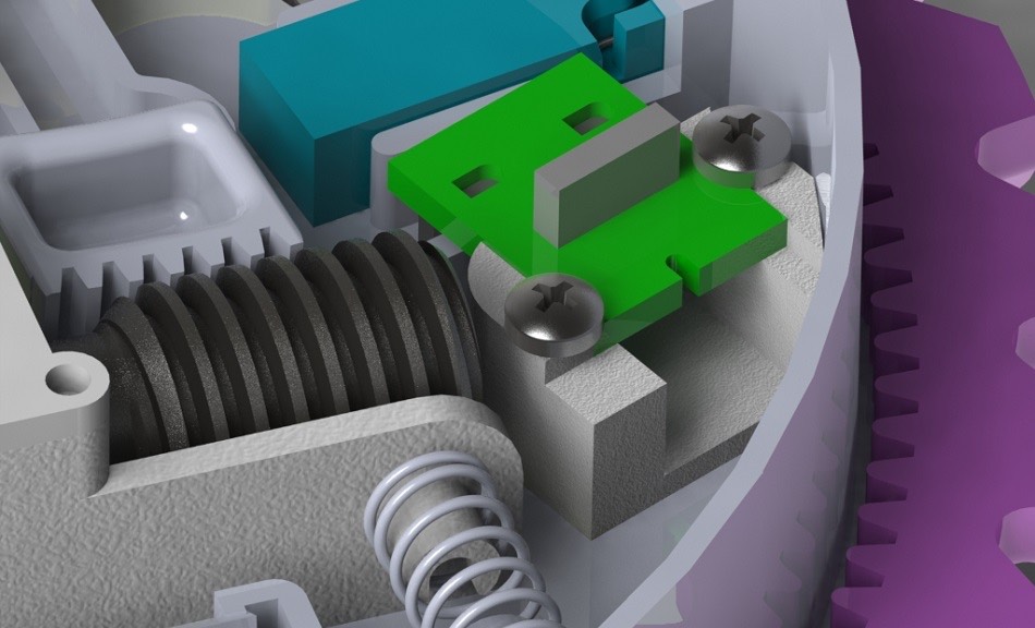
Worm gears are a little more flexible: When a worm interacts with a spur gear, it can be a very effective reducer (worm gears commonly act as a single-tooth gear, with just one long “tooth” wrapped around the shaft, so you get phenomenal reductions in a single step, eliminating a complex gearbox). But worms are also commonly used in linear actuators, where the worm (or screw) has a nut moving along its length, translating rotary motor motion into a low-backlash linear movement.
Backlash? What’s that? Glad you asked. Backlash in gear systems is the amount of movement you can get at one end of the system, when the other end of the system is stationary.
For instance, if you have a loose gear box, you may be able to rotate the output shaft by several degrees, even when the motor on the input shaft is completely fixed. You can feel this in your car when you’re on a hill; even after you shut down the engine and put the car in gear, it still moves when you let off the brake. Ideally, we want to minimize the amount of backlash in a gear system to keep the movement predictable.
We also want to design gears that have smooth, constant power transfer, but there’s a common problem with that in spur gears, unless you get the shape just right.
For example, let’s imagine we create two gears in the shape of stars, as in the image below. The gear on the left is the drive gear (attached to a motor) and the gear on the right is receiving the power and is connected to a wheel. What will happen when we try to drive this robot forward?
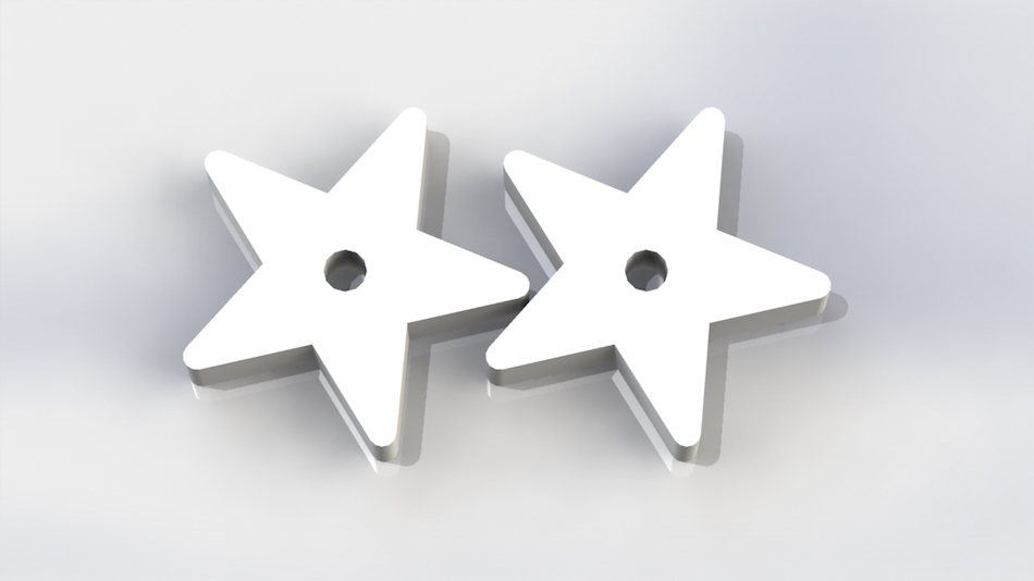
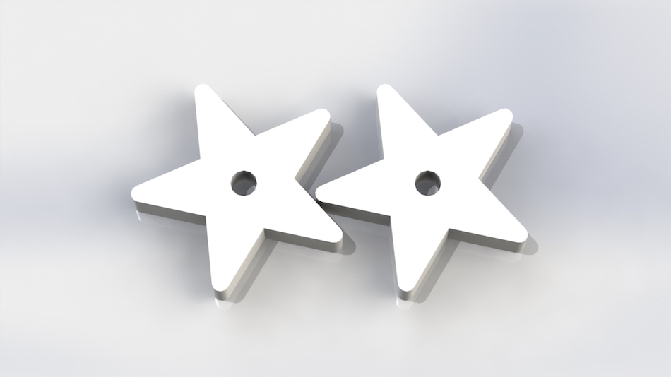
At the beginning, the drive gear has a point pushing against the indent on the wheel gear. The leverage is low, because the lever arm from the center of the gear to the point is much further than the indent to the point (image on the left). But as the two gears rotate, the situation reverses, and the drive gear will have strong leverage (as in the image on the right).
This means that if the motor has constant power, and the wheel has constant resistance force, that the resulting motion will be jerky. As much as that makes for cool robot dancing, it’s not great in your creation. What’s the solution?
Fortunately, gearing systems have been around for long enough that there’s a great geometric solution to this problem: involute gear teeth. Say what?
Involute teeth allow for smooth power transfer by keeping constant ratios of leverage between the two gears, and they do this by imitating a perfect pulley system. (Not to be confused with the torso-defining perfect pushup system, though this design will have your robot looking two-syllable fine.)
Imagine that instead of gears you have two posts, and a string is wound around one post many times and also wrapped around a second post. As we wind more string onto the second post, the first post will rotate; and more importantly, the rotation and power transfer between these two posts will be smooth and constant. Involute gear design imitates this ideal scenario by shaping the teeth of the gears in the shape of the string unwinding.
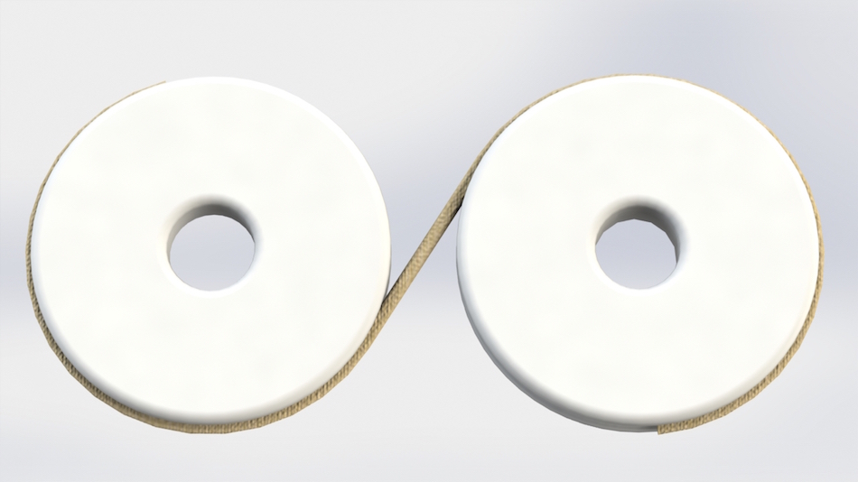
And this is where we need to think about pressure angle again. If the two pulleys or posts are in contact, then the pressure angle would be zero degrees, and there would be no room for our gear teeth.
The further apart we place the two base circles—the two circles representing the perfect pulleys—the higher our pitch angle. High pitch angles become more efficient for power transmission, but at the expense of space and quietness; a 20-degree pressure angle is typical in most gearing systems for a good balance of properties.
Designing Involute Gears in CAD/CAM
Unfortunately, most CAD programs don’t have a button for “create involute gears,” so you’ll have to create these geometries manually. Fortunately, the process is pretty simple, once you see it in action, and it’s well worth it to have a smooth robot. I’ll walk you through the process in SolidWorks in this tutorial, and you can use a similar system for any other program.
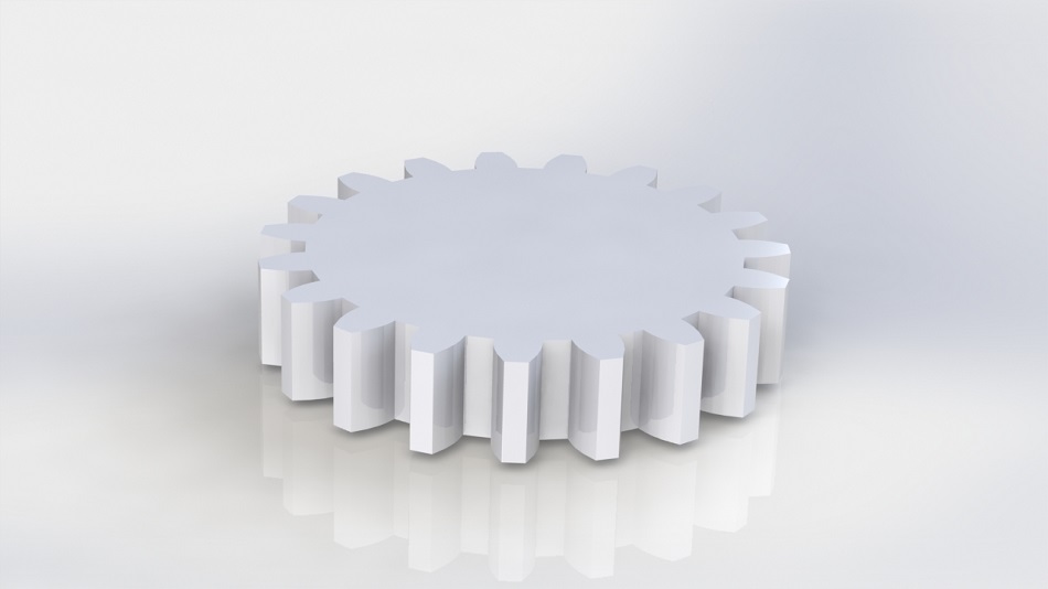
So now you have a nearly-perfect 3D gear in SolidWorks—can you print it out and throw it into your design? Almost, but it’s not quite that simple.
3D Printing Gears
As with any manufacturing method, in order to get a good final product, you need to look at the reasonable tolerances for how your design is being produced, and this is especially important for 3D printed gears.
With a machined metal gear on a good CNC machine, it’s easy to produce gears with tolerances of as little as 0.005 inches. This means that you can expect good-quality gears all the way down to about 64 pitch with no problem at all, and can even produce 128-pitch gears if needed. But with some 3D printing methods, your tolerances may be as much as 0.020”—four times the size—and you’ll want to scale up the gears accordingly.
How small is too small?
For my designs, I use the 10x rule of thumb: the pitch should be ten times the size of the tolerance. That means that a minimum tooth size for an FDM printed gear with 0.020” tolerance would be 0.20”—basically, you can have 5-pitch gears easily printed. If you’re willing to do a little sanding on the final product, then you can lower that to a 5X design rule, but I would recommend going for a finer-tolerance process, such as SLS, instead, which, with its 0.010” tolerance, can easily create gears in the 10-pitch range.
The table below shows recommended printing methods for different gear pitches. Though it’s only a guide, this has worked well for my robotics designs in the past, and I would recommend following it until you have more experience.

Overprinting and Friction in 3D Prints
A word of warning: Not all 3D printing services are equal. When machines are set up, they have to be calibrated to achieve their ideal tolerances, and not all printing services go to the trouble of doing so. For instance, most un-calibrated FDM machines will consistently print with dimensions about 0.5 mm (0.020”) larger than the 3D model file.
Fictiv’s machines have been calibrated so that the expected tolerance is reliably just 0.25 mm. This doesn’t mean you can’t use a high school science lab’s printer for robotic parts, but it does mean that you should allow for the extra pitch size needed to make the parts run smoothly.
Similarly, when choosing how to print your design, take a moment to think about materials and finishes. Printing methods like PolyJet create very smooth surface finishes, which is great for reducing friction. Similarly, SLS Nylon is a great low-friction material, but because SLS has a rough, powdery surface finish, your designs will require some light sanding to operate well.
Take a moment to check out our guide to materials and the notes on low-friction materials in our article on design for moving parts to get more info.
Applied Robotics
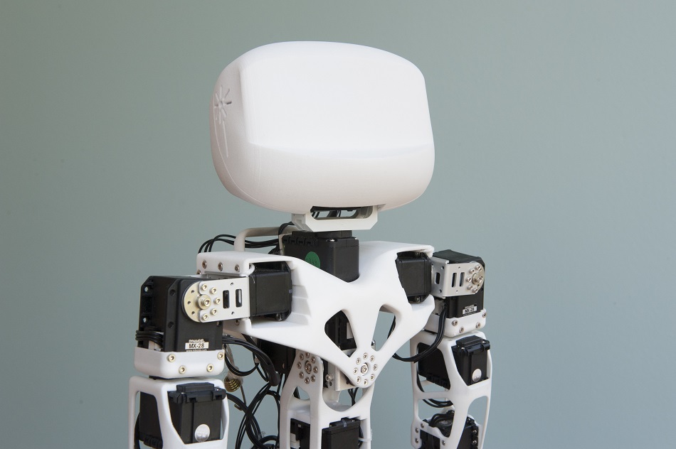
Maybe you won’t be designing the next Jetson family maid or Iron Man suit, but with a little geometric design and consideration of materials, bringing your next robotic design to life in 3D print is absolutely doable.
Have a design you’re ready to print? Check out our 3D printing services to get started.
Know another dreamer who wants to design and build a robot? Feel free to send this article to them to help make their dreams a reality!

